Table 27: Ethernet and Serial Link (BT8A78ESL1) Specifications (continued)
SpecificationItem
Link (right): Green when the link is up on the corresponding CMM
management port.
Activity (left): Not used. This LED is green when the Link LED is lit.
NOTE: The Link LED reflects the status of the link on the corresponding
port of the CMM. If you connect a device to a port on the ESL module but
leave the corresponding port on the CMM unconnnected, the Link LED
will not light up. Conversely, if you connect a device directly to a CMM
port, the corresponding Link LED on the ESL module might light up even
if no cable is connected to the ESL module.
Port LEDs
Chassis Alarm Panel (CAP)
•
BTI7814 CAP on page 65
•
BTI7802 CAP on page 66
•
BTI7801 CAP on page 67
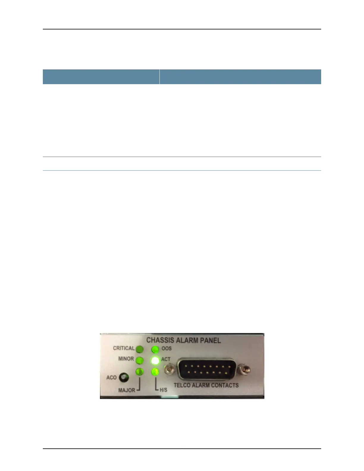
BTI7814 CAP
The BTI7814 Chassis Alarm Panel (CAP) provides a set of relay contacts to signal alarms
to an external device, for example a breaker interface panel. The contacts are designed
with shielded cable that is grounded at both the device and Front Panel Display interface.
The CAP is accessible through the top rear of the chassis, and the display is located at
the top right of the chassis front.
The CAP provides the following indications and functions:
•
Alarm Cutoff (ACO)/Lamp test button.
•
Alarm LEDs
•
Telco (Office) Alarm Connector (for pin assignments and input voltages, see Telco
Alarm Connector Pin Assignments)
Figure 21: BTI7814 Chassis Alarm Panel
65Copyright © 2019, Juniper Networks, Inc.
Chapter 2: BTI7800 Series Chassis

 Loading...


