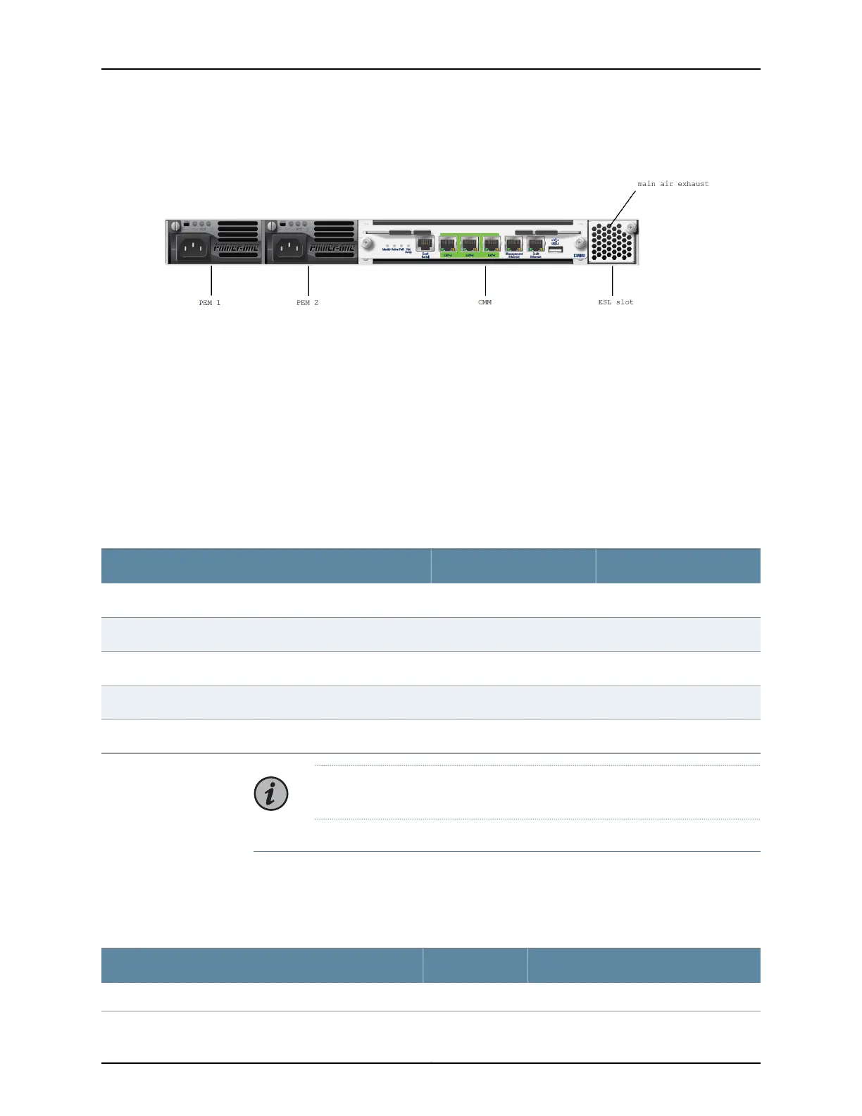
Figure 7: BTI7801 Chassis Rear View
To provide front access to management ports and chassis alarm indicators, the BTI7801
cooling module is fitted with management ports and chassis status LEDs. For the
management ports to be operational, the 1-Slot Chassis Front Cooling Module (FAN5)
must be deployed with the optional Ethernet and Serial Link (ESL) module. The ESL
module extends management connectivity from the rear of the chassis to the front. It
connects to the FAN5 module from the rear and connects to the CMM using external
cables.
The LEDs provide a visual indication of the chassis alarm status and do not require the
ESL module.
Table 14: BTI7801 Common Equipment Components
Release IntroducedPECComponent
Release 2.1BT8A78ESL1Ethernet and Serial Link (ESL) module
Release 2.1BT8A78FAN51-Slot Chassis Front Cooling Module
Release 1.3BT8A78PEM1-DC1-Slot/2-Slot Chassis DC Power Entry Module
Release 1.3BT8A78PEM1-AC1-Slot/2-Slot Chassis AC Power Entry Module
Release 1.1BT8A78CMM1Chassis Management Module (CMM)
NOTE: The ESL module is optional and must be ordered separately.
BTI7801 Chassis Kits
The BTI7801 can be ordered as a kit that includes the bare chassis along with common
equipment modules, tools, and installation hardware. The following lists the chassis kits
available for the BTI7801:
Table 15: BTI7801 Kits
Component PECQuantityMain Equipment Included
Equipment common to all BTI7801 kits
Copyright © 2019, Juniper Networks, Inc.38
BTI7800 Series Hardware Overview and Installation Guide

 Loading...


