•
Multimeter
•
Chassis Installation Kit (BT8A7865)
•
Chassis Crimp Lug Installation Kit (BT8A7867). The dual stud lugs supplied in the
Chassis Crimp Lug Installation Kit are for use with 2 AWG cables. The 2 AWG lugs can
crimp down to 4 AWG.
•
A set of power cables that meets the requirements specified in “BTI7814 DC PEM
Specifications” on page 43
1. Verify that there is no power going to the chassis.
2. Verify that the chassis is properly grounded. For information on frame-grounding the
chassis, refer to “Frame-Grounding a BTI7814 Chassis” on page 89.
3. Prepare the power cables as needed for attachment to the chassis.
a. Use a wire stripper tool to strip one end of the power cable to the correct length
(5.0 mm, 0.2 inch) for crimping on the supplied (dual stud) ring lugs.
b. Insert the stripped end of the power cable into the open end of the lug.
c. Use a ring lug crimping tool (do not use pliers) to secure the power cable to the
lug.
4. Remove the protective shields covering the DC PEMs (if applicable).
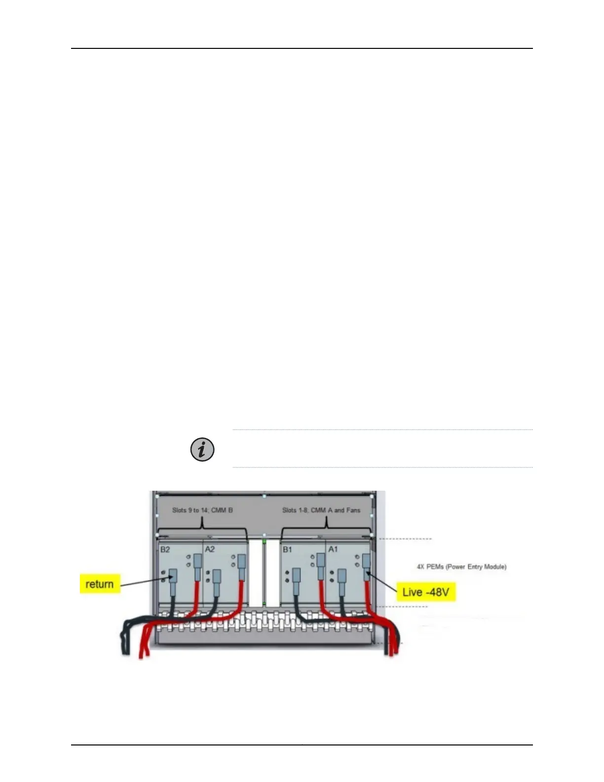
5. Connect the power feeds as follows.
NOTE: All four feeds must be connected for proper operation.
Figure 27: DC PEM Power Feed Connections
a. Connect the first set of Feed and Return cables to the first DC PEM.
Copyright © 2019, Juniper Networks, Inc.96
BTI7800 Series Hardware Overview and Installation Guide

 Loading...


