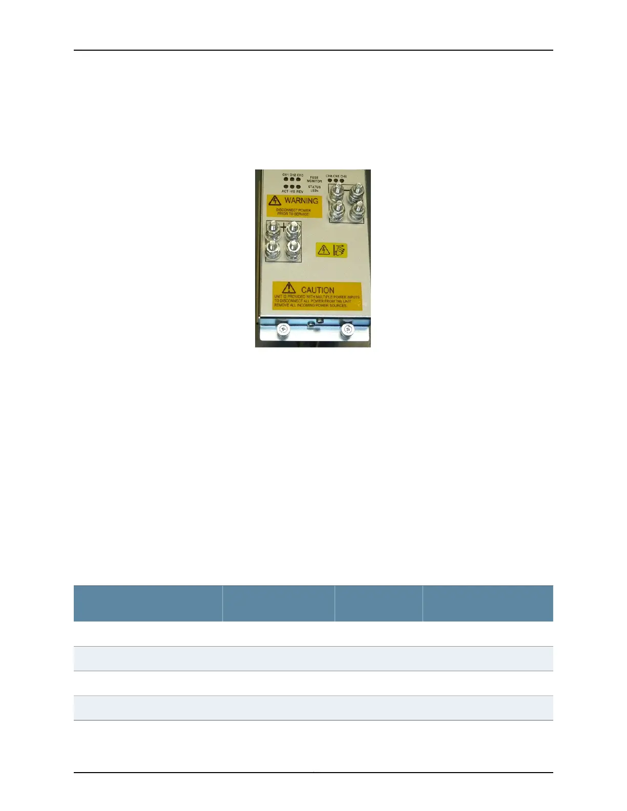
Each DC PEM features two dual-stud return terminals and two dual-stud feed terminals.
Typically, only one dual-stud terminal is used. The extra dual-stud terminals can be used
for particular applications, such as laboratory applications.
Figure 8: BTI7814 14-Slot Chassis DC Power Entry Module
The DC PEMs are located on the rear of the chassis. The slots are numbered PEM 1 through
PEM 4 (from right to left). PEM 1 and PEM 2 power one set of six channels, and PEM 3 and
PEM 4 power the other set of six channels. For details on the power distribution plan, see
“BTI7814 Power Distribution Plan” on page 40.
There is a direct correlation between the DC PEM slots and the internal shelf input
terminals.
The external A feed pair consists of two individual feeds, A1 and A2, which connect to
the external input terminals of PEM 1 and PEM 3. The DC outputs of PEM 1 and PEM 3
supply power to the A1 and A2 internal shelf input terminals respectively.
Similarly, the external B feed pair consists of two individual feeds, B1 and B2, which
connect to the external input terminals of PEM 2 and PEM 4. The DC outputs of PEM 2
and PEM 4 supply power to the B1 and B2 internal shelf input terminals respectively.
This is shown in the following table along with the external breaker requirements for each
individual feed:
External Breaker
Requirements
Internal Shelf Input
TerminalsDC PEM SlotsExternal Feeds
125AA1PEM 1A1
125AB1PEM 2B1
125AA2PEM 3A2
125AB2PEM 4B2
Copyright © 2019, Juniper Networks, Inc.42
BTI7800 Series Hardware Overview and Installation Guide

 Loading...


