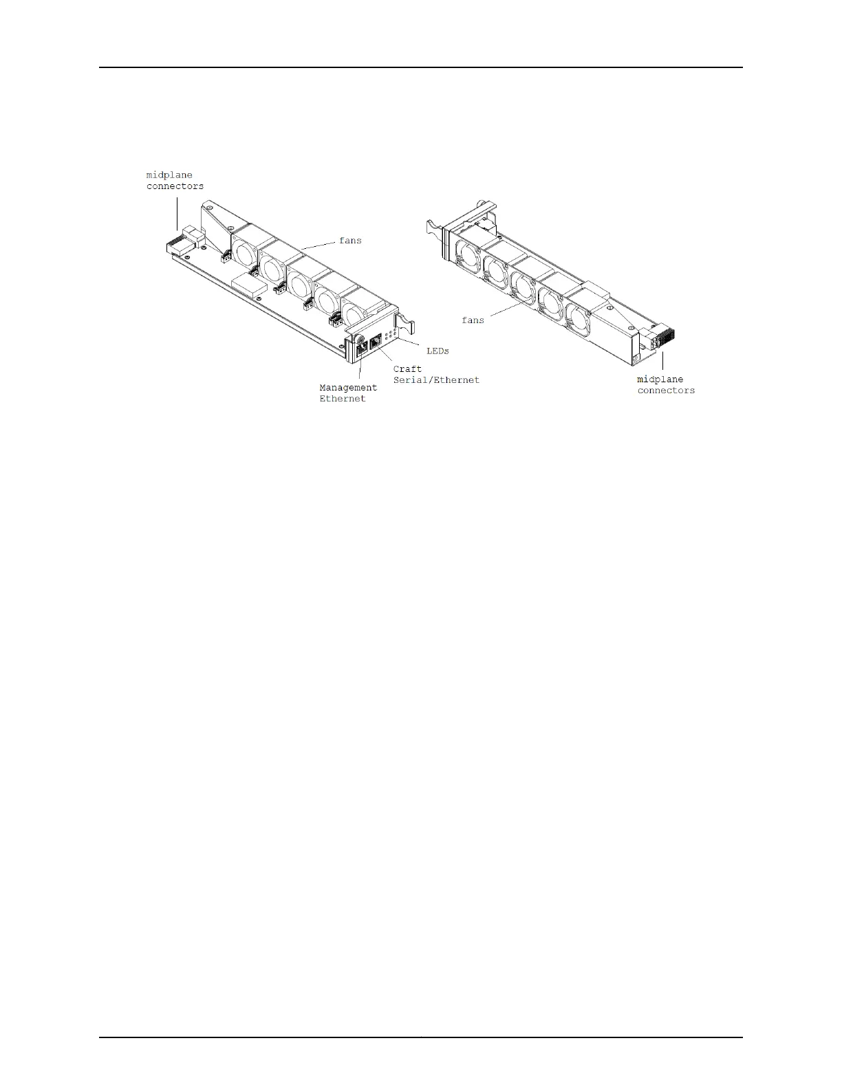
Figure 18: 1-Slot Chassis Front Cooling Module (BT8A78FAN5)
Figure 19 on page 62 shows the airflow through the chassis. Outside air enters the chassis
through the air intake above the service module slot. The fans draw the air into the fan
module slot and blow the air along the ESL module slot towards the main chassis air
exhaust at the rear. Openings in the ESL slot allow some air to flow across the CMM and
out the secondary air exhaust above the CMM.
If AC PEMs are installed, the internal AC PEM fans draw air into the module and exhaust
the air out along the midplane transverse airflow channel where the air eventually mixes
with the main chassis airflow. This channel is located between the front and rear
backplanes.
61Copyright © 2019, Juniper Networks, Inc.
Chapter 2: BTI7800 Series Chassis

 Loading...


