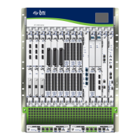
Table 17: BTI7814 Backplane DC Power Distribution
ModulesSlotChannelInput Feeds
Service ModulesService module slots 3
and 4
1A1 and B1
Service ModulesService module slots 5
and 6
2
Service ModulesService module slots 7
and 8
3
Service ModulesService module slots 1
and 2
4
BTI7814 Booster FansRear fans 5 and 65
Chassis Management Module (CMM)CMM slot A6
Front Fan modulesFront fans 1, 2, 3 and 4
Service ModulesService module slots 11
and 12
1A2 and B2
Service ModulesService module slots 13
and 14
2
Not applicableFuture use3
Not applicableFuture use4
Service ModulesService module slots 9
and 10
5
Chassis Management Module (CMM)CMM slot B6
Not applicableFuture use
Each channel has a fuse rating of 20 Amps.
BTI7814 DC PEM
The BTI7814 chassis can be powered by up to four DC PEMs (BT8A78PEM3-DC). Two
DC PEMs are used to provide the A feeds, for a total of twelve channels on the chassis.
Each DC PEM powers six channels that feed various functions. A non-redundant
configuration requires two DC PEMs. A redundant configuration requires four DC PEMs.
It is recommended that you configure your chassis with four DC PEMs and connect each
PEM to its own (separate) power supply and return.
41Copyright © 2019, Juniper Networks, Inc.
Chapter 2: BTI7800 Series Chassis

 Loading...


