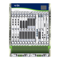
Installing and Cabling the BTI7802 DC PEM
This topic describes how to install, cable and connect power to the BTI7802 1-Slot/2-Slot
Chassis DC Power Entry Modules (BT8A78PEM1-DC).
NOTE: BTI7800 equipment should be powered in accordance with DC-I
(isolated DC return) equipment installation criteriathe DC return terminal is
not connected to the equipment frame or the equipment grounding means.
For procedures to replace a DC PEM, refer to “Replacing the BTI7802 PEM” on page 193.
WARNING:
This equipment is intended to be installed and serviced by qualified
personnel.
•
•
To avoid personal injury or damage to chassis components, ensure there
is no power going to the chassis.
•
Make sure you are familiar with the site and safety guidelines described in
the BTI7800 Series Hardware Overview and Installation Guide.
WARNING: Before you proceed:
•
Do not work alone.
•
The chassis must be grounded to the frame in which it is mounted.
•
The power source to which you are connecting the chassis must be powered
off.
•
The circuit breaker switch, to which the power source is wired, must be
shut off.
•
Locate the emergency power-off switch for the location in which you are
working.
•
Do not overload the power source to which you are connecting the chassis.
•
Check your work area for possible hazards, such as ungrounded power
extension cables and moist floors.
•
Remove all jewelry, neckties, and scarves.
•
Use appropriate caution. This documentation does not cover every potential
hazardous condition.
Installation Tools and Kits
•
Wire stripping and crimping tool
101Copyright © 2019, Juniper Networks, Inc.
Chapter 4: Installing the BTI7800 Series Chassis

 Loading...


