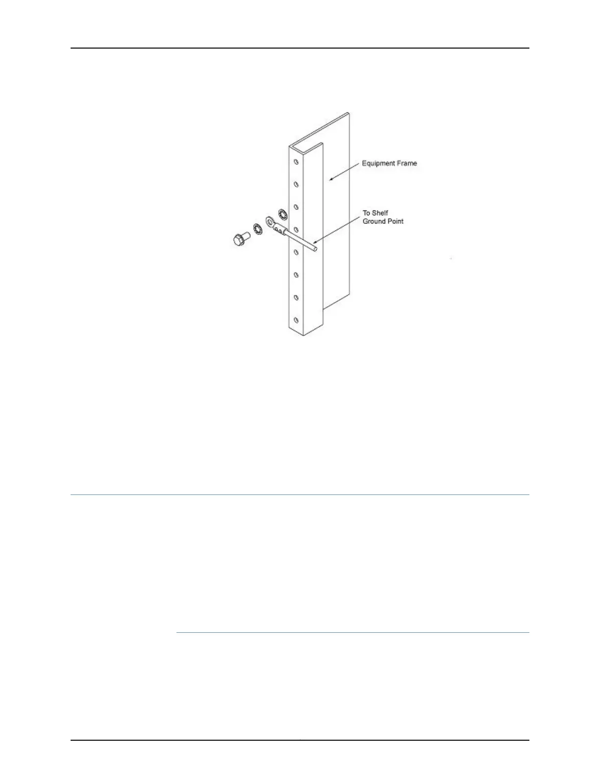
6. Check the connectivity of the grounding by using a multimeter to measure the
resistance between the shelf and the frame. Put one test lead in contact with an
unpainted zone of the chassis and the other test lead in contact with the equipment
frame. The measured resistance should be less than 1 Ohm.
You have successfully completed this procedure.
Powering the Chassis
•
Powering the BTI7814 Chassis on page 94
•
Powering the BTI7802 Chassis on page 100
•
Powering the BTI7801 Chassis on page 105
Powering the BTI7814 Chassis
•
Connecting the DC Power Feeds to a BTI7814 DC PEM on page 94
•
Connecting the AC Power Feeds to a BTI7814 AC PEM on page 97
Connecting the DC Power Feeds to a BTI7814 DC PEM
If you order the BTI7814 chassis with the DC option, the chassis is shipped with the 14-Slot
Chassis DC Power Entry Modules DC PEM installed. This topic describes how to connect
the power feeds to the DC PEMs.
Copyright © 2019, Juniper Networks, Inc.94
BTI7800 Series Hardware Overview and Installation Guide

 Loading...


