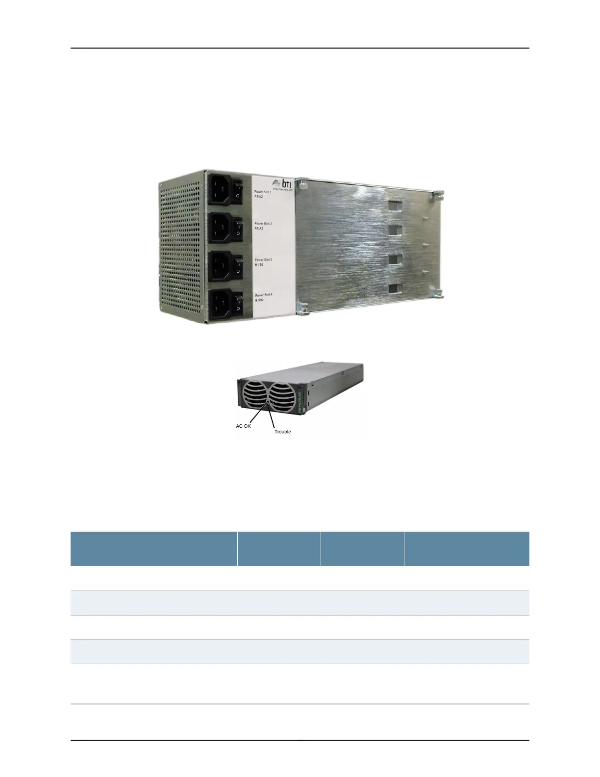
The AC PEM rectifier housing (Figure 9 on page 45) is 4RU tall, and can contain up to
four AC PEMs. The rectifier housing and rectifiers come pre-installed on the chassis when
you order the chassis with the AC option.
Figure 9: BTI7814 AC PEM Housing
Figure 10: BTI7814 AC PEM Rectifier
Each rectifier (Figure 10 on page 45) is 1RU tall, and is cooled using internal fans. The
rectifier slots are numbered from Slot 1 (top) to Slot 4 (bottom). The top two rectifiers
are for the A feed pair, while the bottom two rectifiers are for the B feed pair. For details
on the power distribution plan, see “BTI7814 Power Distribution Plan” on page 40.
The external fuse/breaker requirements for each feed is shown in the following table:
External Breaker
Requirements
Internal Shelf Input
TerminalsAC PEM SlotsExternal Feeds
20AA1/A2Slot 1
1
A1
20AA1/A2Slot 2
1
A2
20AB1/B2Slot 3
2
B1
20AB1/B2Slot 4
2
B2
1
The DC outputs of the AC PEMs in Slot 1 and Slot 2 are tied together to supply the A1 and A2 feeds.
2
The DC outputs of the AC PEMs in Slot 3 and Slot 4 are tied together to supply the B1 and B2 feeds.
45Copyright © 2019, Juniper Networks, Inc.
Chapter 2: BTI7800 Series Chassis

 Loading...


