6. Check the connectivity of the grounding by using a multimeter to measure the
resistance between the shelf and the frame. Put one test lead in contact with an
unpainted zone of the chassis and the other test lead in contact with the equipment
frame. The measured resistance should be less than 1 Ohm.
You have successfully completed this procedure.
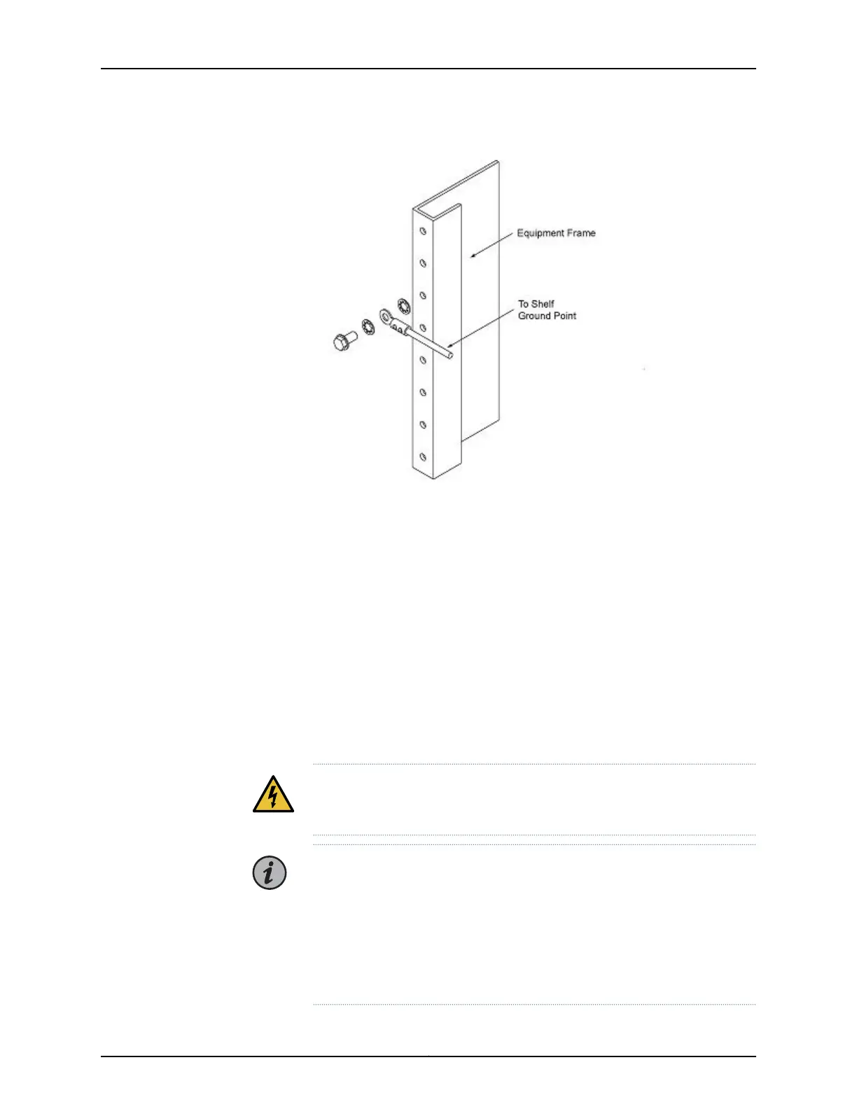
Frame-Grounding a BTI7801 Chassis
The BTI7801 uses DC-I grounding configuration with the return ground isolated from the
frame ground.
WARNING: You must complete this procedure before connecting power and
powering on the chassis. The chassis voltage is considered hazardous.
NOTE: NEBS Compliance Statements for GR-1089:
•
Only copper cables are to be used for grounding purposes.
•
The grounding conductor AWG size should match the size of the power
cable AWG.
•
Bare conductors must be coated with antioxidant before crimp connections
are made.
Copyright © 2019, Juniper Networks, Inc.92
BTI7800 Series Hardware Overview and Installation Guide

 Loading...


