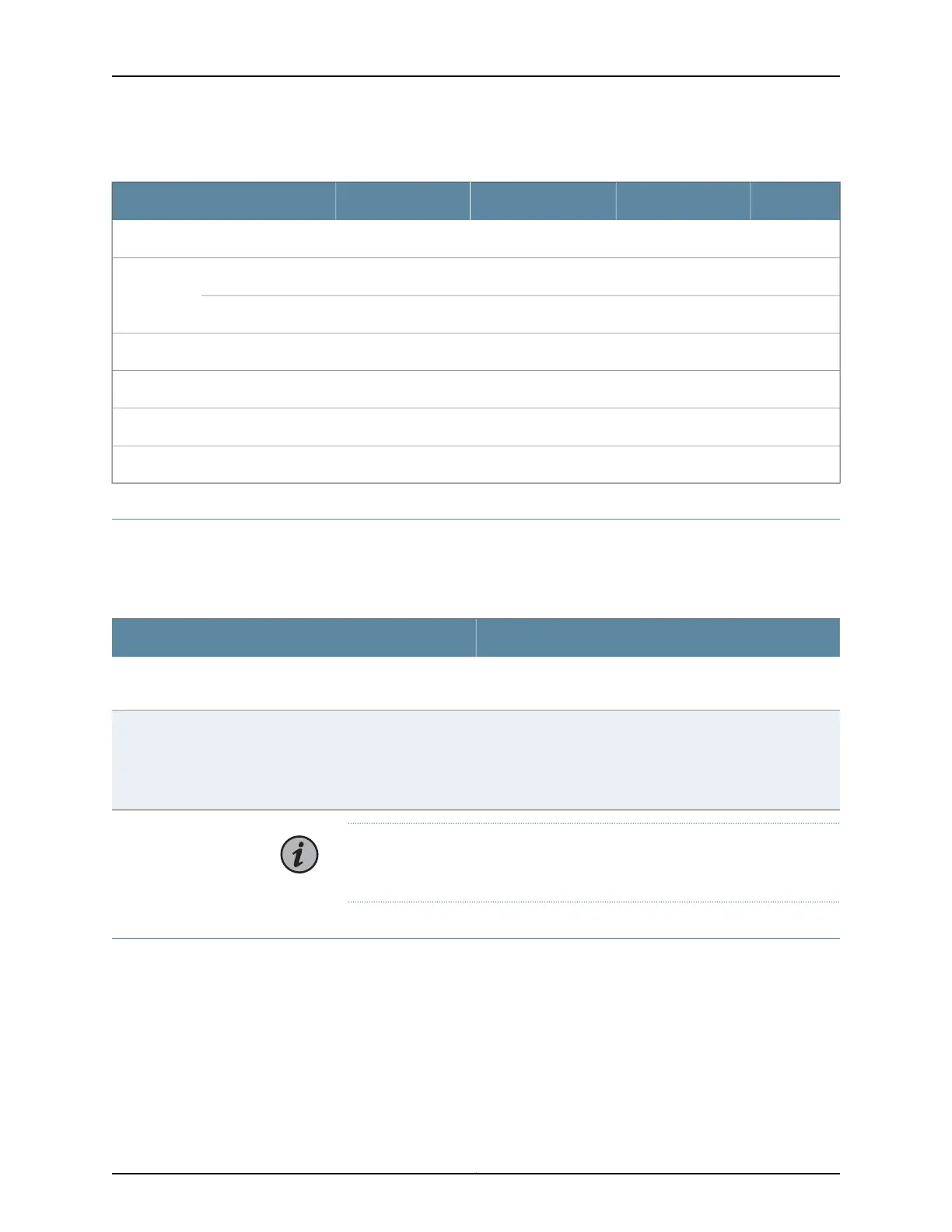
Table 76: 400G Coherent MSA XCVR (2 X 200-Gbps) on UFM6 (continued)
UnitsMaximumTypicalMinimumParameter
dB––3PDL tolerance
ps/nm30000–-3000016-QAMDispersion
tolerance
ps/nm70000–-70000QPSK
dB––27Optical return loss from receiver
Other
W125115–Power Consumption
LC/UPCConnector
Installation Rules for the 100G Coherent CFP
The following rules must be followed when installing the 100G Coherent CFP (BP3AMCTL,
CFP-100GBASE-CHRT) in a BTI7814 chassis.
Table 77: Installation Rules for the 100G Coherent CFP in a BTI7814 Chassis
DescriptionRule
The 100G Coherent CFP must be installed in a BIC in BIC slot
2 of the UFM (lower slot of the UFM when viewed vertically).
Placement within the UFM
The UFM with the 100G Coherent CFP must be installed to the
immediate right of a fully occupied slot, or in slot 1 (leftmost
slot) of the chassis. A fully occupied slot is a slot that contains
a module. If that module is a UFM, then that UFM must have
BIC modules in all of its BIC slots.
Placement within the chassis
NOTE: Failure to comply with these rules might lead to adverse thermal
behavior and premature failure.
Cleaning Transceivers
When cleaning transceivers, use an industry standard fiber optic cleaner or a 1.25 mm
cotton-tipped swab to insert into the receptacle. The swabs can be used to clean the
optical surface and to clean debris from the inner sleeve. Use extreme care as it is easy
to scratch the optical plane.
177Copyright © 2019, Juniper Networks, Inc.
Chapter 6: BTI7800 Series Transceiver Specifications

 Loading...


