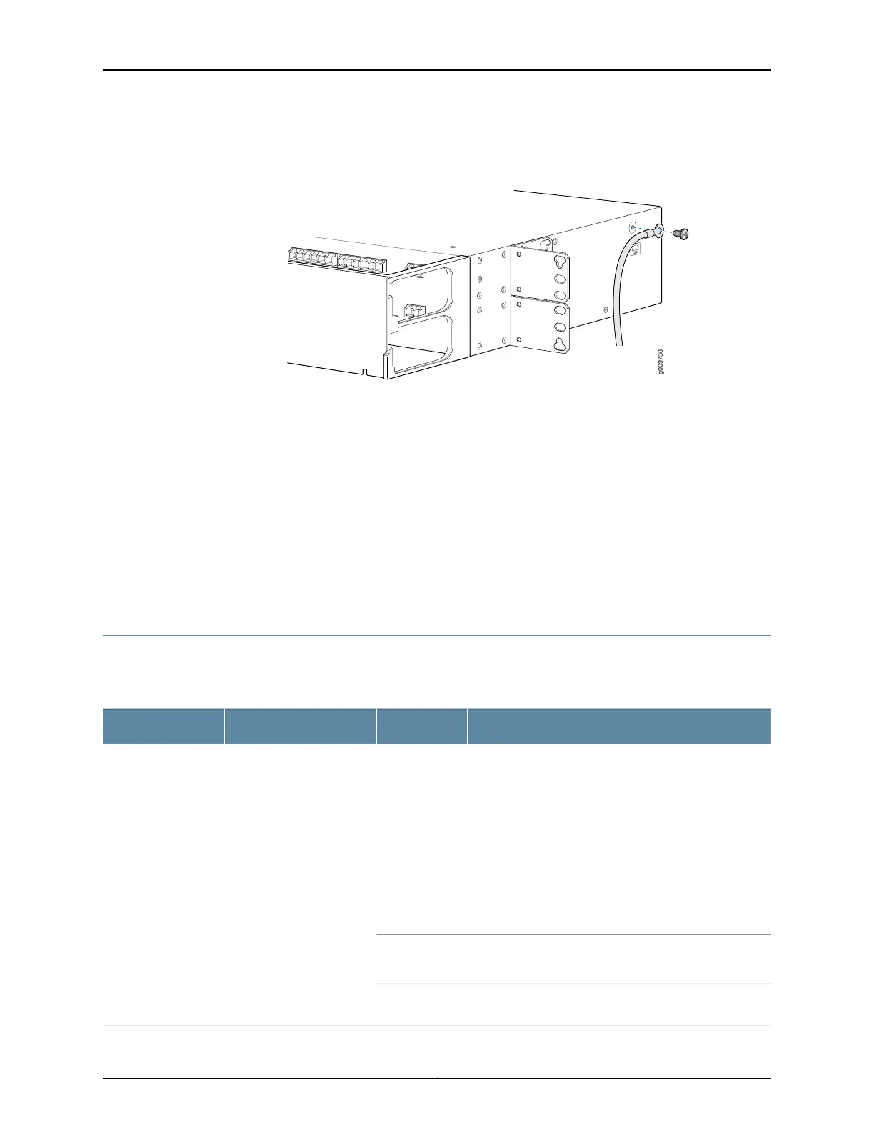
Figure 51: Remove the Lug
3. Remove the FMD96 from the frame or the rack.
a. Position one person on each side of the FMD96 to secure the FMD96 during removal.
b. Remove the mounting screws and washer for each mounting bracket attachment.
c. Remove the FMD96 from the frame or the rack.
d. Place the FMD96 in antistatic packaging and stow in accordance with the
environmental storage conditions.
You have successfully completed this procedure.
Service Module LEDs
The following table describes the LEDs for all service modules.
Table 52: Service Module LED Behavior
State DescriptionStateDescriptionName
The CMM has identified and acknowledged the module.
The CMM can only acknowledge the module if the
module is administratively up. A newly-inserted module
is administratively up if either of the following is true:
•
The module has been pre-provisioned and configured
to be administratively up.
•
Auto-provisioning is enabled. If auto-provisioning is
enabled and if the CMM is able to identify the module,
the module is automatically provisioned and its
administrative status is set to up.
OFFThe Identify LED indicates
whether the CMM has
identified and
acknowledged the
newly-inserted module.
Identify
(AMBER)
The CMM has failed to identify or acknowledge the
module.
ON
The CMM is attempting to identify and acknowledge the
module.
BLINKING
151Copyright © 2019, Juniper Networks, Inc.
Chapter 5: BTI7800 Series Modules

 Loading...


