}
}
The output shows a basic connectivity configuration. Verify that the values displayed are
correct for your services gateway.
Related
Documentation
SRX650 Services Gateway Software Configuration Overview on page 97•
• Performing Initial Software Configuration on the SRX650 Services Gateway Using the
Setup Wizard
• Configuring Basic Settings for the SRX650 Services Gateway with the CLI or the J-Web
Interface on page 113
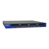
Built-In Ethernet Ports for the SRX650 Services Gateway
You performinitial device setup through the four built-in Gigabit Ethernet ports, ge-0/0/0
through ge-0/0/3, on the front panel of the SRX650 Services Gateway.
NOTE: If chassis clustering is enabled, we recommend using the ge-0/0/0
port as the management port (fxp0) and using the ge-0/0/1 port (if used) as
the control port (fxp1). The fxp0 and fxp1 ports are created only when chassis
clustering is enabled. You can use the other ports as fabric ports.
Before initial configuration, when the factory default configuration is active, the services
gateway attempts to perform autoinstallation by obtaining a device configuration through
all its connected interfaces, including ge-0/0/0. All interfaces are configured as Layer 3
interfaces. See Table 31 on page 118 for the default interface configuration.
Table 31: Default Interface Configuration for the Services Gateway
AddressDHCP StateSecurity ZoneInterface
Dynamically assignedClientUntrustge-0/0/0
NOTE: If chassis
clustering is enabled,
use this port as the
management port
(fxp0).
192.168.1.1/24.ServerTrustge-0/0/1 (if used)
NOTE: If chassis
clustering is enabled,
use this port as the
control port (fxp1).
192.168.2.1/24ServerTrustge-0/0/2 (if used)
NOTE: Use this port
as a fabric port.
Copyright © 2018, Juniper Networks, Inc.118
SRX650 Services Gateway Hardware Guide