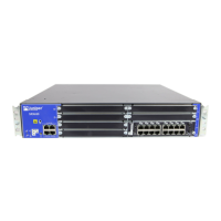
Table 34: Component LEDs on the Services Gateway Chassis (continued)
UsageLocationLED
The SRE/ACE 1.1 LED has the
following indicator colors:
•
Green and steadily on indicates
ACE 1.1 half slot is functioning
normally. Not applicable with
SRE full slot module.
•
Amber and steadily on indicates
ACE 1.1 half slot is initializing,
performing diagnostics, or going
down. Not applicable with SRE
or ACE full slot modules.
•
Red and steadily on indicates
ACE 1.1 half slot failure. Not
applicable with SRE or ACE full
slot modules.
•
Off indicates ACE 1.1 half slot is
empty.
NOTE: ACE modules are currently
not available for ordering, but might
be supported in a future release.
Left side of the front chassis
panel
SRE/ACE 1.1
Related
Documentation
SRX650 Services Gateway Front Panel on page 18•
• SRX650 Services Gateway Back Panel on page 24
• Troubleshooting with Chassis and Interface Alarm Messages on the SRX650 Services
Gateway on page 129
• Troubleshooting the Power System on the SRX650 Services Gateway on page 132
• Using the RESET CONFIG Button on the SRX650 Services Gateway on page 135
• Changing the RESET CONFIG Button Behavior on the SRX650 Services Gateway on
page 136
Troubleshooting with Chassis and Interface Alarm Messages on the SRX650 Services
Gateway
When the services gateway detects an alarm condition, it lights the red or yellow alarm
LED on the front panel as appropriate. To view a more detailed description of the alarm
cause, issue the show chassis alarms CLI command.
There are two classes of alarm messages:
•
Chassis alarms—Indicate a problem with a chassis component such as the cooling
system or power supply.
•
Interface alarms—Indicate a problem with a specific network interface.
129Copyright © 2018, Juniper Networks, Inc.
Chapter 21: Troubleshooting Components

 Loading...


