• SRX650 Services Gateway Rack Size and Strength Requirements on page 47
• Connecting the SRX650 Services Gateway to the Building Structure on page 69
Clearance Requirements for Airflow and Hardware Maintenance of the SRX650 Services
Gateway
When planning the installation site for the SRX650 Services Gateway, you need to allow
sufficient clearance around the rack.
When planning the installation site for the services gateway, consider the following:
•
For the cooling system to function properly, the airflow around the chassis must be
unrestricted. The fan tray contains four fans and provides side-to-side chassis cooling.
Figure 11 on page 49 shows the direction of airflow through the chassis.
•
For service personnel to remove and install hardware components, there must be
adequate space at the front and back of the services gateway as indicated in
Table 12 on page 48 .
•
If you are mounting the services gateway in a rack with other equipment, ensure that
the exhaust from other equipment does not blow into the intake vents of the chassis.
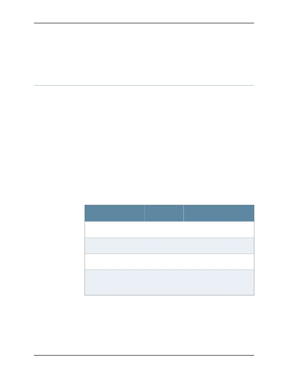
Table 12 on page 48 provides information about the clearance requirements for
maintaining optimum airflow and the distances to facilitate easy maintenance of the
services gateway.
Table 12: Clearance Requirements for the SRX650 Services Gateway
Requirement for Clearance
Recommended
ClearanceLocation
Space for service personnel to remove
and install hardware components
8.7 in (22 cm)Front of the chassis
Space for service personnel to remove
and install hardware components
17.4 in (44.2 cm)Rear of the chassis
Space for cable management and
organization
2.5 in (6.35 cm)Between front-mounting flange
and rack or cabinet edge
Space for the cooling system to
function properly and to maintain
unrestricted airflow around the chassis
6.0 in (15.24 cm)Between both sides of the
chassis and any
non-heat-producing surface
such as a wall or cabinet side
Copyright © 2018, Juniper Networks, Inc.48
SRX650 Services Gateway Hardware Guide