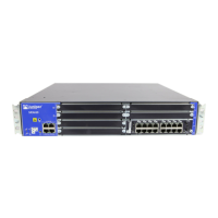
Table 34: Component LEDs on the Services Gateway Chassis (continued)
UsageLocationLED
The SRE 0 LED has the following
indicator colors:
•
Green and steadily on indicates
SRE0 is functioning normally.
•
Amber and steadily on indicates
SRE0 is initializing, performing
diagnostics, or going down.
•
Red and steadily on indicates
SRE0 failure.
•
Off indicates SRE0 slot is empty.
Left side of the front chassis
panel
SRE 0
The SRE/ACE 1.0 LED has the
following indicator colors:
•
Green and steadily on indicates:
•
SRE1 is functioning normally.
•
ACE 1.0 half slot is functioning
normally.
•
ACE 1 full slot is functioning
normally.
•
Amber and steadily on indicates
SRE1/ACE1 (full slot) or ACE 1.0
(half slot) is initializing,
performing diagnostics, or going
down.
•
Red and on steadily indicates
SRE1/ACE1 (full slot) or ACE 1.0
(half slot) failure.
•
Off indicates SRE/ACE1 slot is
empty.
NOTE: ACE modules are currently
not available for ordering, but might
be supported in a future release.
Left side of the front chassis
panel
SRE/ACE 1.0
Copyright © 2018, Juniper Networks, Inc.128
SRX650 Services Gateway Hardware Guide

 Loading...


