Keysight N9038A MXE Service Guide 161
Input Selection & Level Control
Input Selection & Level Control Section Troubleshooting
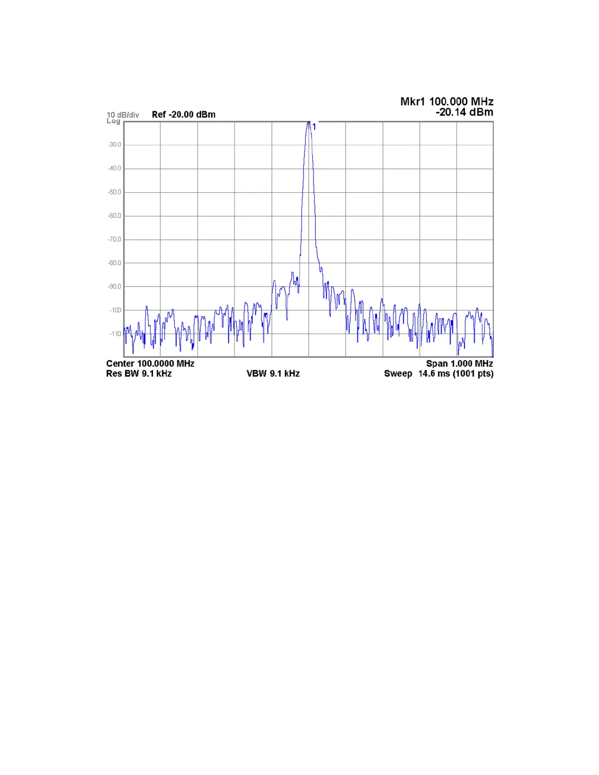
Figure 4-24 SW2 Transfer Switch Signal Level
12.Move the spectrum analyzer to the SW2 Transfer Switch Transfer Out (P2)
port, as shown in Figure 4-21.
13.Switch the instrument to use the RF preselector, which will connect the
SW2 Transfer Switch RF Input (P1) to the Transfer Out (P2) port, by
pressing Input / Output, RF Input, RF Preselector On.
14.Verify that the signal level on the spectrum analyzer is at −20 dBm
(±0.25 dB), as shown in Figure 4-24, allowing for any additional test cable
loss.
If the signal level is incorrect the most likely cause of the problem is the
SW2 Transfer Switch itself. However, before replacing an SW2 Transfer
Switch for any failure, refer to the “A21 RF Preselector Input Assembly”
section on page 175 for information on how to verify the control signals to
it.
15.Move the signal generator to the SW2 Transfer Switch Transfer In (P3)
port, as shown in Figure 4-21.
16.Move the spectrum analyzer to the SW2 Transfer Switch RF Output (P4),
as shown in Figure 4-21.
17.Verify that the signal level on the spectrum analyzer is at −20 dBm
(±0.25 dB), as shown in Figure 4-24, allowing for any additional test cable
loss.

 Loading...


