Keysight N9038A MXE Service Guide 255
RF Downconverter Section
RF Downconverter Section Troubleshooting
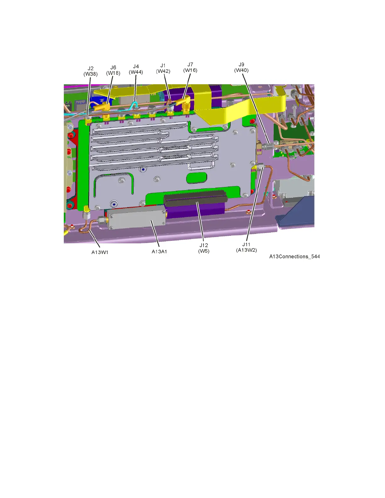
Figure 6-18 A13 RF Front End Assembly Connections - Option 544
4. Connect a spectrum analyzer to the A13 RF Front End assembly Output
(J7).
5. Tune the spectrum analyzer to 322.5 MHz with a span of 10 MHz.
6. Turn the instrument on and allow it to complete its boot up process.
7. Turn the instrument self-alignment routine off by pressing System,
Alignments, Auto Align, Off.
8. Tune the instrument to 100 MHz with a span of 0 Hz by pressing FREQ,
100 MHz and SPAN, Zero Span.
9. Referring to Figure 6-17 or Figure 6-18, disconnect W38 from the A13 RF
Front End assembly low band Input (J2).
10.Connect a signal generator to the A13 RF Front End assembly low band
Input (J2).
11.Tune the signal generator to 100 MHz with an amplitude of -30 dBm.
12.Verify that the signal amplitude on the spectrum analyzer display is
approximately -25 dBm (5 dB gain), allowing for any additional test cable
loss, as seen in Figure 6-19.

 Loading...


