Keysight N9038A MXE Service Guide 293
Front End Control
A15 Front End Control Assembly Troubleshooting
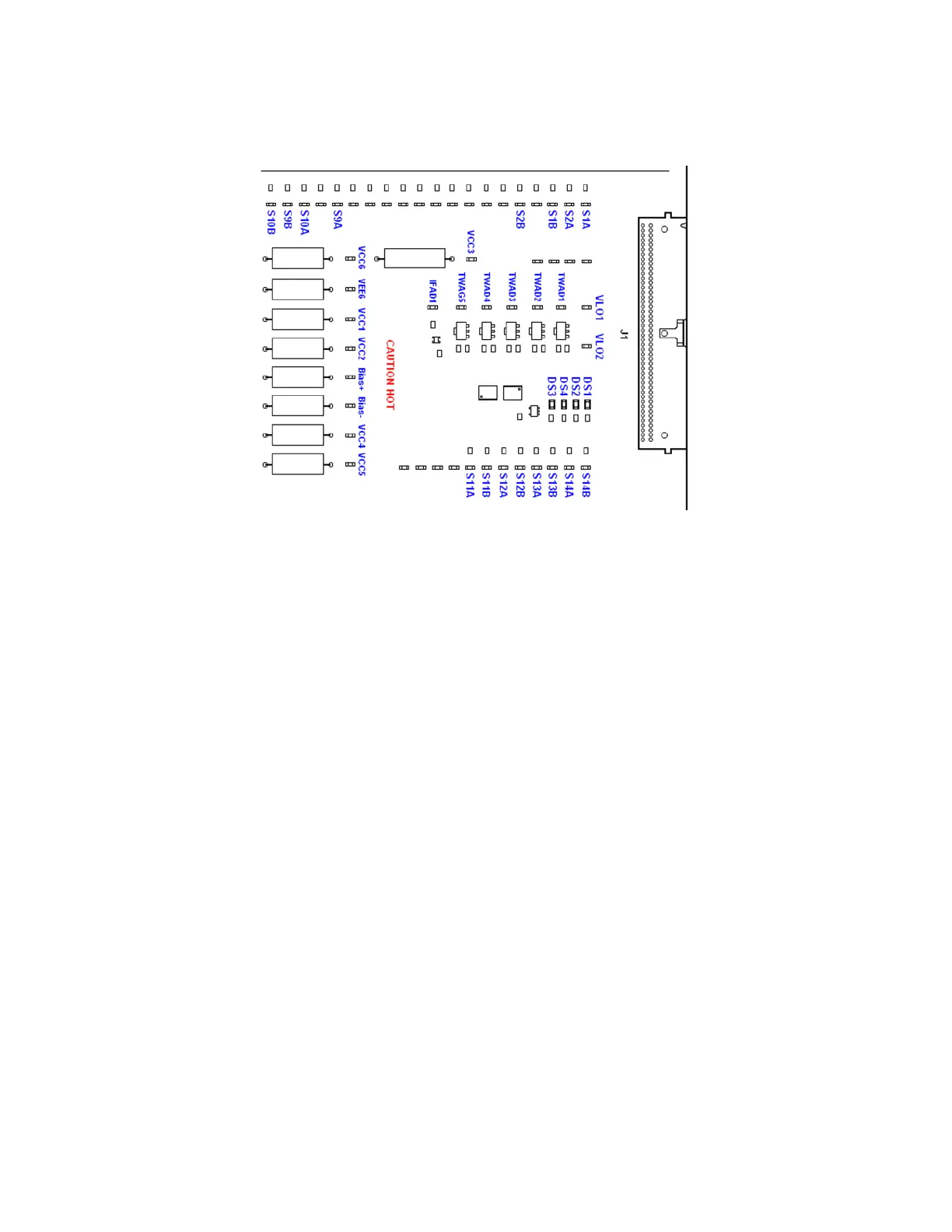
Figure 8-12 A13 RF Front End Assembly Control Front End Test Board
Verifying the Control for the A13 RF Front End Assembly
1. Remove the instrument dress cover (MP24) and top brace (MP10). Refer to
Chapter 18, “Assembly Replacement Procedures.” for instructions on
removing these covers.
2. Disconnect cable W5 from J104 as shown in Figure 8-6.
3. Connect the A13 RF Front End Assembly Control cable from J104 to the
Front End Control Test board J1 as shown in Figure 8-3.
4. Place the Front End Control Test board on a non-conductive surface.
5. Turn the instrument on and allow it to complete its boot up process,
ignoring any alignment failures.
6. Turn the instrument auto alignment routine off by pressing System,
Alignments, Auto Align, Off.
7. Referring to Figure 8-12, verify that all four of the power supply voltage
LEDs on the Front End Test board for the A13 RF Front End assembly are
on. If one or more of the power supplies is not on verify the A6 Power
Supply output voltages before replacing the A15 Front End Control
assembly. For information on verifying the A6 power supply output
voltages see Chapter 12, “Power Supply & Midplane.”.

 Loading...


