Seat Tracks
If equipped, seat tracks are marked with station identication markings every
10 inches, starting at FS (Fuselage Station) 50.0. These markings will assist
the operator in quickly installing seats. Refer to the following example of how
to properly install a seat.
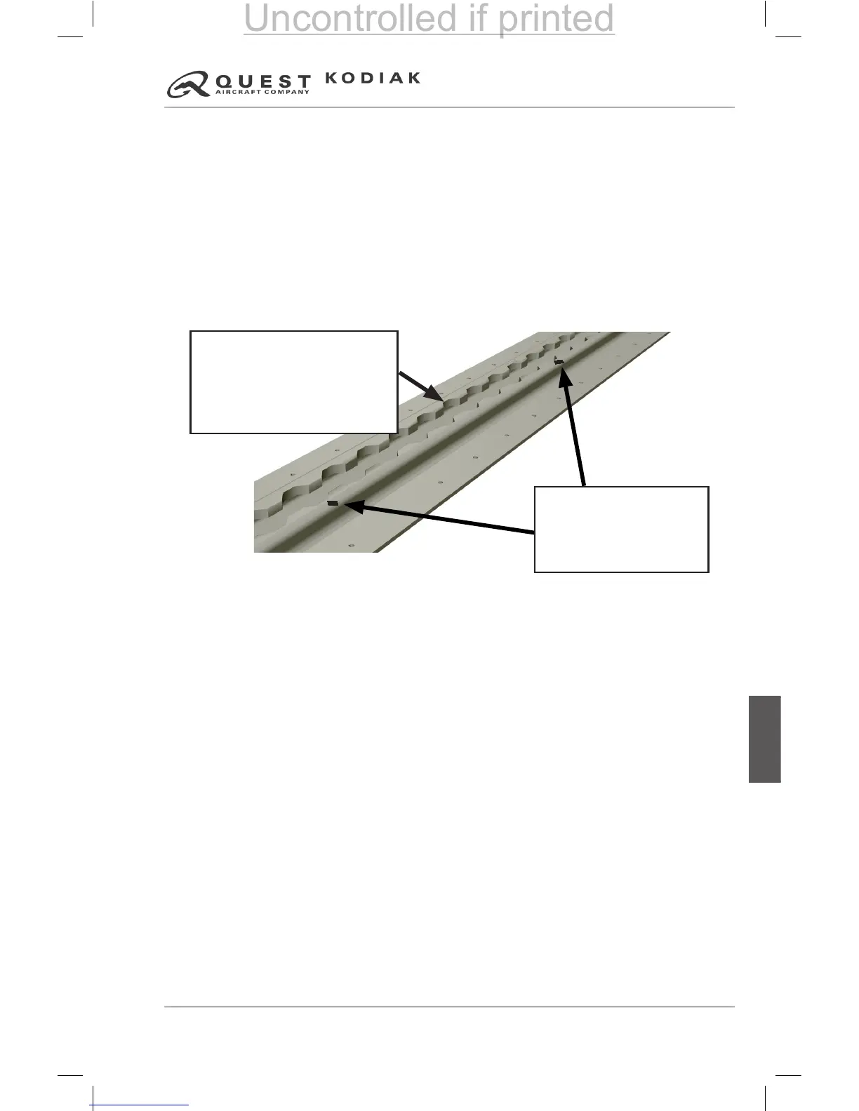
Example: To install a seat in Row 3 (FS 115.0), locate fuselage station
marking FS 110.0 and count 5 seat track notches AFT. Insert the seat lock
paw into FS 115.0 and move the seat 1/2 inch AFT and engage the seat track
lock. This is the location for the center of the seats track lock pin. For gures
and instructions regarding Passenger and Crew seat installation and removal,
refer to “Section 7” of this manual.
Figure 6-1 – Seat Track Marking Example
If the seats are moved from the above locations, the individual seat weights
and seat CG locations are provided below for calculations.
Crew Seat (with Belts)
Weight ................................ See seat weights on Weight and Balance form
Seat Reference Point
................ Center of track lock pin and rear foot pivot
FS of Crew Seat Rear Stop
................................... Conguration A - 50.0 in.
Conguration B - 44.0 in.
Seat CG (occupied and unoccupied)
...See Weight & Balance Calculations
Minimum Seat Pitch* between Crew Seats rear stop and
Passenger Seats (second row)
........................................................ 34.0 in.
Passenger Seat (with Belts)
Weight ................................ See seat weights on Weight and Balance form
Seat Reference Point
.............................................. Center of track lock pin
Seat CG (occupied and unoccupied)
...See Weight & Balance Calculations
Minimum Seat Pitch* between rows
................................................. 31.0 in.
*Seat pitch is the distance between the AFT locking mechanism of the seat, to the
AFT locking mechanism of the seat behind it. For the second row of passenger
seating (Row 2), seat pitch is the distance between the center of the Crew Seat Rear
Stop and the AFT locking mechanism of the seat behind it.
 Loading...