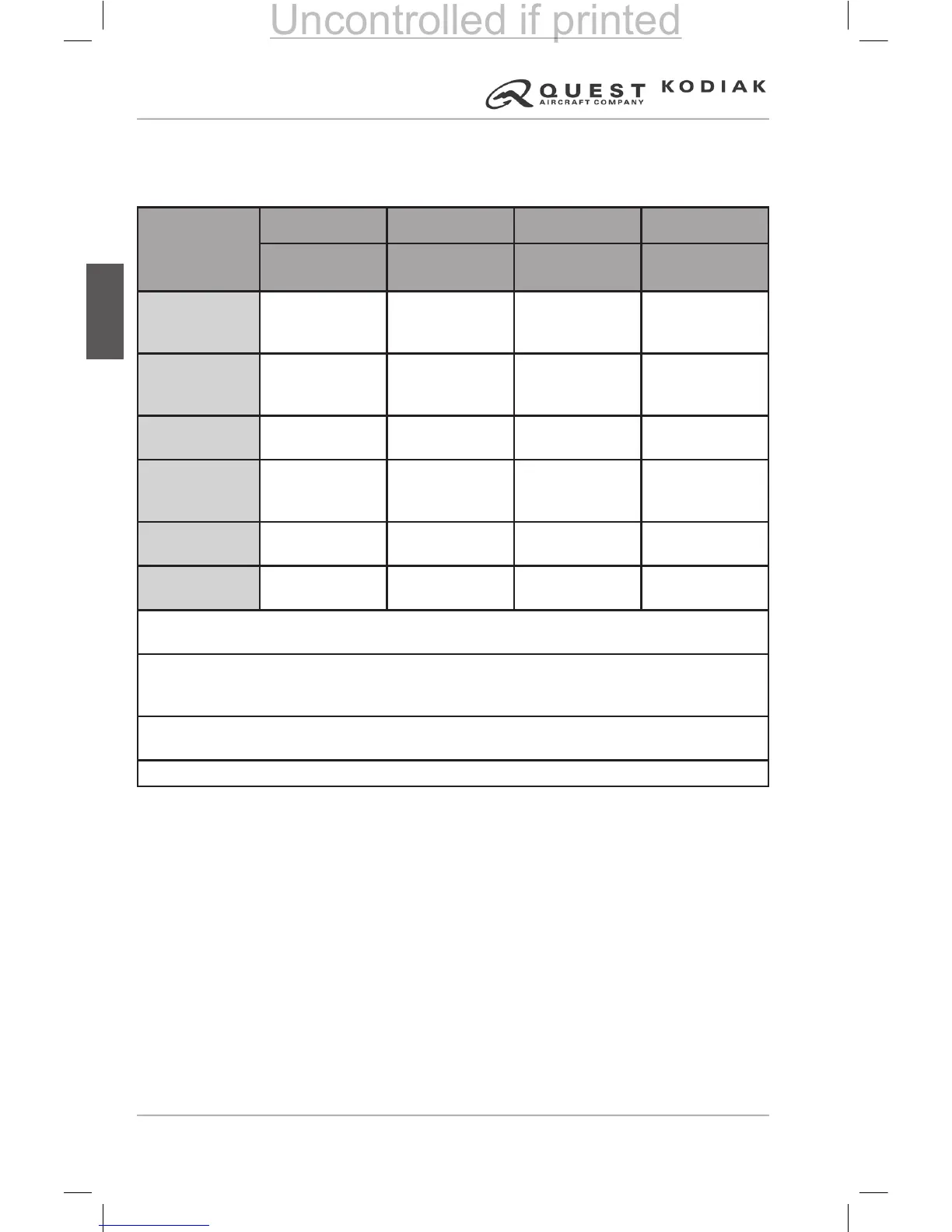
2-5 POWER PLANT INSTRUMENT MARKINGS
Marking designations for the power plant instruments are provided in the table
below and the gure on the following page.
Instrument
Red Line Green Arc Yellow Arc Red Line
Minimum
Limit
Normal
Operating
Caution
Range
Maximum
Limit
Torque
Indicator
(2)
—
0 to 1670 ft-lb
Variable to 1840
(1)
1670 to 1790 ft-lb
Variable to 1970
(1)
1790 ft-lb
Variable to 1970
(1)
Inter-Turbine
Temperature
(ITT) Indicator
—
400 to 740°C
(3)
741 to 790°C
(3)
790°C
(3)
Propeller RPM
Indicator
—
1900 to 2200
RPM
450 to 1050
RPM
2200 RPM
Gas Generator
%RPM Indicator
(4)
— 53 to 101.6% — 101.6%
Oil Pressure
Gage
40 PSI 85 to 105 PSI 40 to 85 PSI 105 PSI
Oil Temperature
Gage
-40°C +10 to +99°C -40°C to +10°C +99°C
NOTE (1): The torque indicator operating ranges and red line vary according to the
corresponding propeller RPM.
NOTE (2): A placard is installed indicating cruise torque limits of 1670 ft-lb @ 2200 RPM and
1840 ft-lb @ 2000 RPM; takeoff torque limits are also listed, as 1790 ft-lb. @ 2200 RPM and
1970 ft-lb. @ 2000 RPM.
NOTE (3): During engine start, the ITT indicator indicates a normal operating range from
200°C to 925°C, a caution range from 926°C to 1090°C, and a red radial line at 1090°C.
NOTE (4): 100% Gas Generator RPM is 37,500 RPM.
Table 2-5 – Power Plant Instrument Markings as Displayed on the G1000
 Loading...