MASTER CONTROL UNIT
The Master Control Unit (MCU) is installed on the forward left portion of the
rewall. The MCU provides the electrical control functions necessary for
operation of the starter generator. It controls the LO/MOTOR function of the
starter generator and the sequencing of the HI/START function. The MCU
provides voltage regulation, over-voltage protection and reverse-current
protection. In the event of an over-voltage or reverse-current condition,
the starter/generator is automatically disconnected from the busses. The
Generator Control Unit (GCU), contained in and controlled by the MCU,
connects the generator output to the airplane buses. If any MCU function
causes the GCU contactors to de-energize, disconnecting the generator from
the system, visual and aural annunciation will be provided through the G1000.
Visual annunciation is displayed as follows:
GEN FAIL
ALTERNATOR CONTROL UNIT
The Alternator Control Unit (ACU) is installed on the forward left portion
of the rewall. The ACU controls the output of the standby alternator.
Alternator failure is detected through the ACU and is annunciated as follows:
ALTERNATR FL
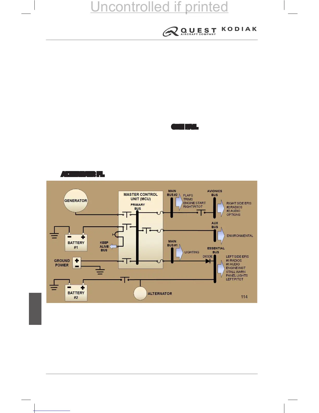
Figure 7-75 – Electrical System Block Diagram
 Loading...