The autopilot roll axis uses an inclined gyro in a turn coordinator which
is installed behind the instrument panel and is not visible for use in ight.
The autopilot uses this turn coordinator as the primary turn and roll rate
sensor. In addition to the turn coordinator instrument, the roll axis computer
computes steering commands for turns, navigation intercepts, and tracking.
Roll axis steering is accomplished by autopilot steering commands to the roll
servo which is installed in the left wing.
The pitch computer receives altitude data from the altitude encoder pressure
transducer which is plumbed into the static system, acceleration information
from an accelerometer, and glideslope information from the HSI and both
NAV radios. Pitch axis command for altitude hold, vertical speed hold, and
glideslope tracking is accomplished by pitch computer commands to the
autopilot pitch servo which is installed in the aft fuselage.
The pitch servo contains a switch to engage the pitch trim servo (auto-trim)
whenever the forces at the pitch servo exceed a set value. The auto-trim
function will not work if the trim disconnect switch (located just forward of the
control yoke) is in the disconnect position. The TRIM annunciation ashing
without any movement of the elevator trim wheel would be an indication of
this.
Altitude preselect is provided through the G1000. An altitude may be
selected using the G1000 Altitude Knobs, the selected altitude is shown
in the window and the altitude bug will be positioned along the altitude
tape. The autopilot will automatically level the airplane off at the selected
altitude when both the VS mode is engaged and the ALT mode is armed.
To accomplish this, simultaneously press the ALT and VS buttons on the
autopilot computer. On the G1000, active modes are annunciated in green
and armed modes are annunciated in white. Therefore, the annunciations
will be shown as
ALT and VS on the G1000.
All autopilot mode selection is accomplished using the mode select
buttons and VS/modier knob on the autopilot computer. Annunciations
for the autopilot system are displayed on both the G1000 and the autopilot
computer. Refer to “Figure S1-3” and “Figure S1-4” for illustrations of the
G1000 annunciations and the autopilot computer annunciations.
FLIGHT DIRECTOR
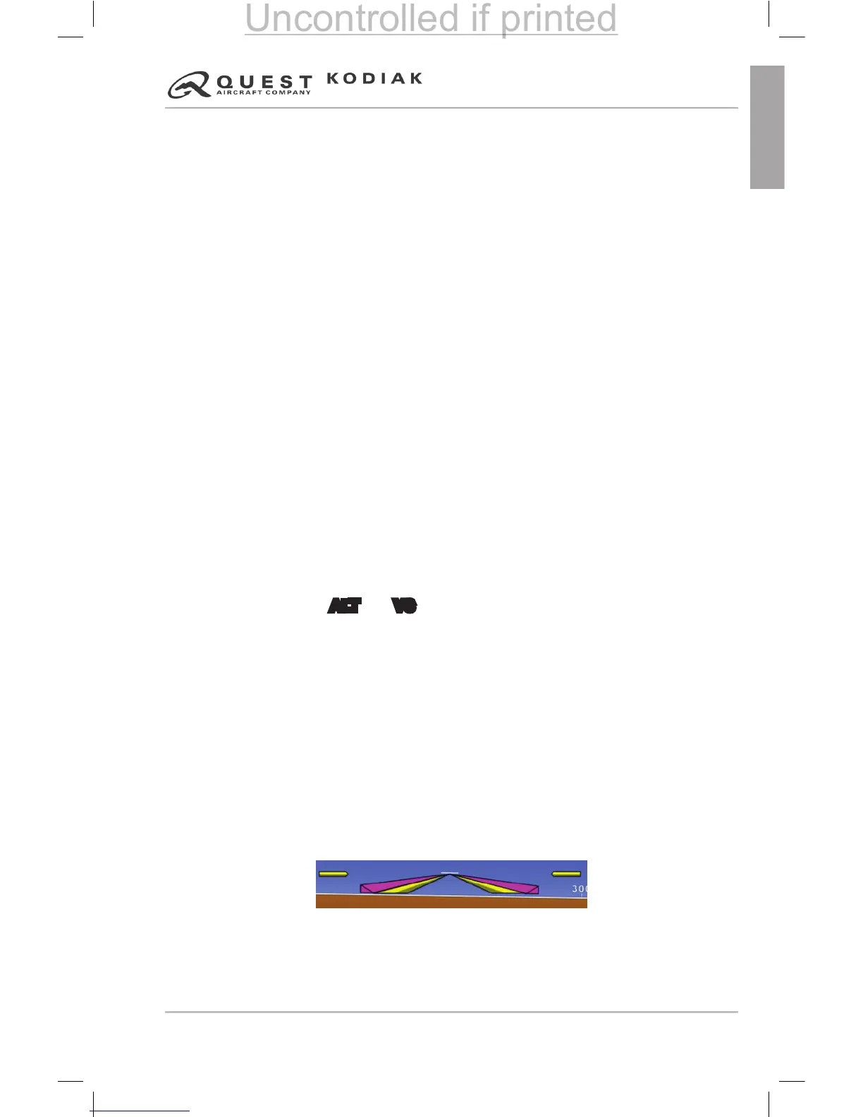
The ight director is a navigational aid that is overlaid on the Attitude
Indicator. This overlay will provide the pilot with visual cues of the suggested
aircraft attitude based on the autopilot mode the pilot has selected (i.e.
heading, altitude, Glideslope). Refer to “Figure S1-6” for detailed mode
information.
Figure 9.1-5 – Flight Director Bars (Magenta)
 Loading...