EasyManuals Logo

Kodiak 100 Series User Manual

Kodiak 100 Series
606 pages
To Next Page IconTo Next Page
To Previous Page IconTo Previous Page
Page #253 background imageLoading...
Page #253 background image
Pilot’s Operating Handbook
7-13
DO NOT USE FOR FLIGHT OPERATIONS
Section 7
AIRPLANE & SYSTEMS DESCRIPTIONS
100 SERIES
Systems
CONTROL PEDESTAL LAYOUT
A control pedestal is installed between the pilot and front passenger seats.
The control pedestal contains the emergency power lever, power lever,
propeller control lever, fuel condition lever, wing ap selector, elevator trim
wheel, rudder and aileron trim switches, rewall fuel shutoff valve control,
microphone, engine control lever friction knob, and the circuit breaker panel.
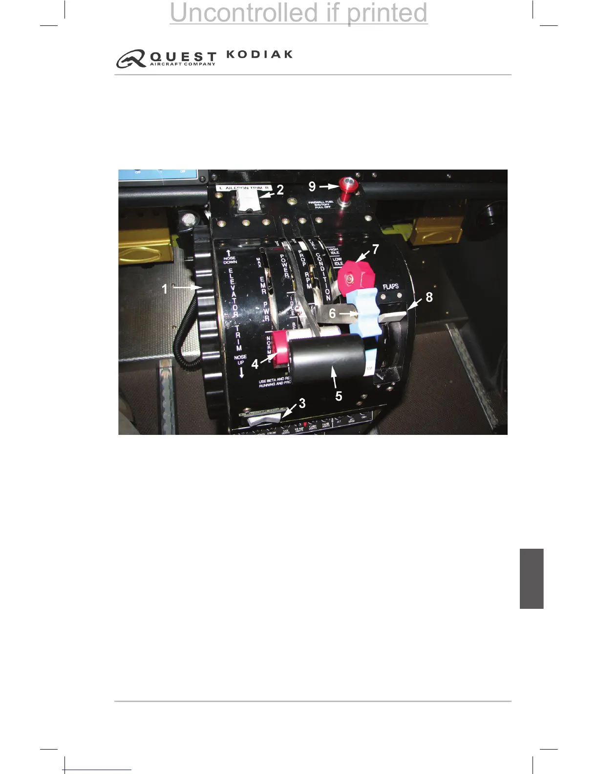
Figure 7-5 – Control Pedestal Layout
1. Pitch Trim Wheel
2. Aileron Trim Switches
3. Rudder Trim Switch
4. Emergency Power Lever
5. Power Lever
6. Propeller Control Lever
7. Fuel Condition Lever
8. Wing Flap Selector
9. Firewall Fuel Shutoff Valve Control
Uncontrolled if printed

Table of Contents

Questions and Answers:

Question and Answer IconNeed help?

Do you have a question about the Kodiak 100 Series and is the answer not in the manual?

Kodiak 100 Series Specifications

General IconGeneral
ManufacturerDaher
EnginePratt & Whitney Canada PT6A-34
Service Ceiling25, 000 feet
Seating Capacity10
Crew1-2
Range1, 132 nautical miles
TypeUtility aircraft
Length34 feet 2 inches
Wingspan45 feet
Max takeoff weight7, 255 pounds
Power Output750 shp
Cabin Width4 feet 6 inches