FLUID QUANTITY INDICATION
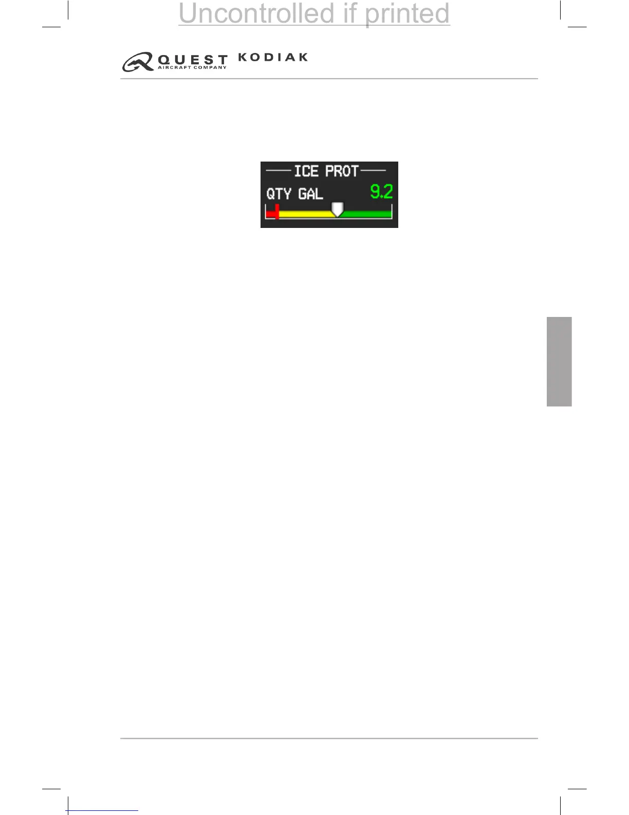
The TKS uid quantity indication is provided through the G1000 on the
Engine Indication System (EIS) on the SYSTEM page. Fluid quantity is
measured by a oat type quantity sensor installed in the ice protection uid
tank.
Figure 9.4-2 – Fluid Quantity Indicator
MODES OF OPERATION
The system is designed for ight into known icing conditions, as dened
by 14 CFR Part 23 and for use in continuous maximum and maximum
intermittent icing envelopes, as dened by 14 CFR Part 25, Appendix C
(for IAC AR certied airplanes, IAC AR Aviation Regulations Part 25,
Appendix C). The HIGH mode provides 100% anti-icing protection to all
leading edge surfaces for all conditions found in the Maximum Continuous
Icing Envelope. NORMAL mode produces cycled ow 30 seconds on and 90
seconds off. During the 30 seconds on time, the ow rate is two times that
of the HIGH mode, but since it runs on a 25% duty cycle, total uid usage
is 50% of the HIGH ow setting. MAXIMUM has two times the ow rate of
HIGH mode and therefore has 200% of the anti-ice ow needed to provide
a clean leading edge in the Maximum Continuous Icing Envelope. BACKUP
mode is the equivalent of HIGH mode, but uses a separate pump than the
HIGH mode.
ICE INSPECTION LIGHTS
To provide visual verication of icing conditions and conrmation of uid
ow, ice inspection lights are ush mounted to the right and left crew doors.
The ice inspection lights illuminate the leading edge of the wings, pitot/static
tubes, stall warning lift transducer, and the upper portion of the wing struts.
System components include the LED light assemblies and a two position
switch labeled ICE LIGHT.
The ice inspection lights operate on 28 VDC and are protected by the 5 amp
circuit breaker labeled ICE INSP LIGHTS. The ice inspection lights switch is
located on the right hand side switch panel.

 Loading...