Pilot’s Operating Handbook
7-20
DO NOT USE FOR FLIGHT OPERATIONS
Section 7
AIRPLANE & SYSTEMS DESCRIPTIONS
100 SERIES
Systems
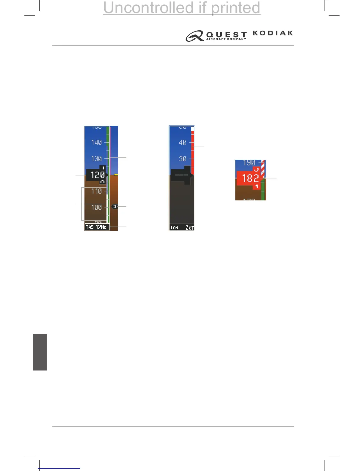
AIRSPEED INDICATOR
The Airspeed Indicator displays airspeed on a moving tape rolling number
gauge. The true airspeed is displayed in knots below the Airspeed Indicator.
The numeric labels and major tick marks on the moving tape are marked at
intervals of 10 knots. The minor tick marks on the moving tape are marked
at intervals of ve knots. Speed indication starts at 20 knots, with 60 knots of
airspeed viewable at any time. The indicated airspeed is displayed inside the
black pointer. The pointer remains black until reaching maximum operating
speed (V
), at which point it turns red.
Figure 7-11 – Airspeed Indicator Ranges
Color coded stripes appear on the Airspeed Indicator to show the operating
ranges. The low speed range stripe is red and extends to the ap operating
range. Normal operating range is green and the maximum operating speed
(V
) begins with a red and white barber pole. The ap operating range is
indicated by a white and two shades of blue stripe.
The Airspeed Trend Vector is a vertical magenta line that appears to the right
of the color-coded speed range strip when airspeed is either accelerating
or decelerating. One end of the magenta line is anchored to the tip of
the airspeed pointer while the other end moves continuously up or down
corresponding to the rate of acceleration or deceleration. For any constant
rate of acceleration or deceleration, the moving end of the line shows
approximately what the indicated airspeed value will be in six seconds. If
the trend vector crosses V
, the number in the indicated airspeed pointer
changes to yellow. The trend vector is absent if the speed remains constant
or if any data needed to calculate airspeed is not available due to a system
failure.
Low
Speed
Range
Red
Pointer
at V
MO
Speed
Ranges
Indicated
Airspeed
Airspeed
Trend
Vector
Vspeed
Reference
True
Airspeed
 Loading...