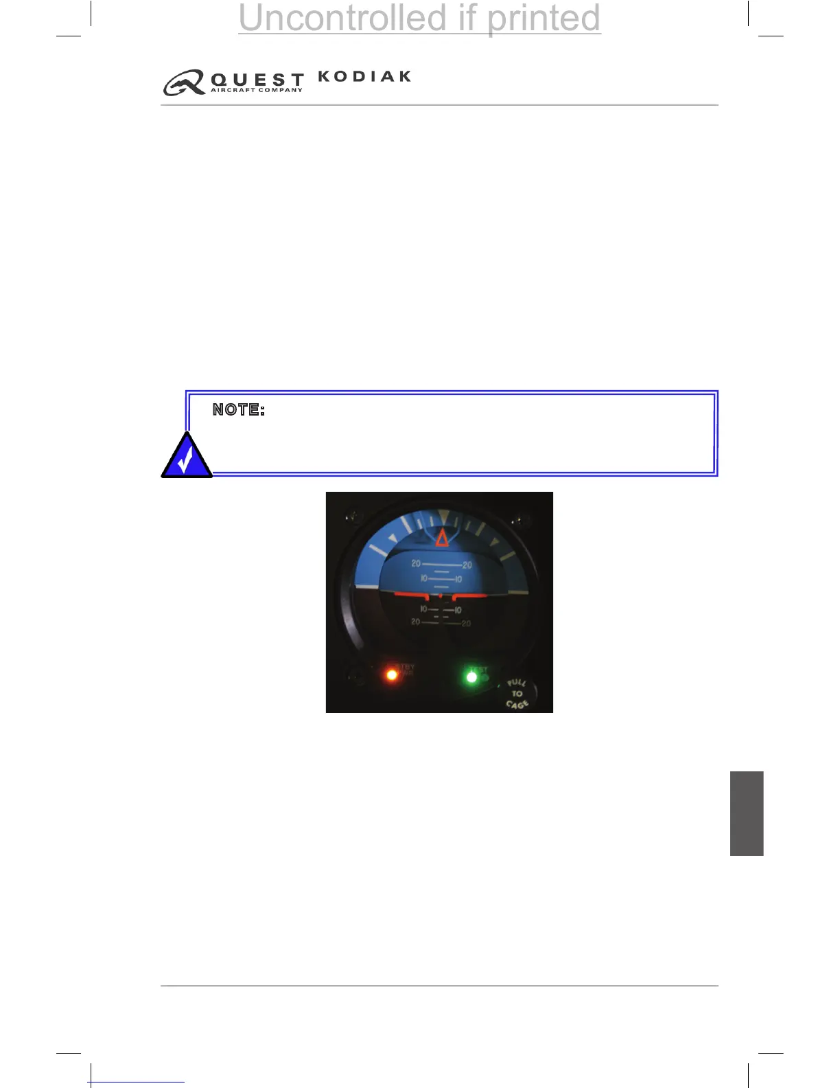
Initiating the Standby Battery Test
1. Turn the indicator on with aircraft power and allow the unit to spin up for a
minimum of 3 minutes.
2. Press and hold the STBY PWR button. After several seconds, the amber
LED will start ashing, indicating the unit has latched into Battery T
est
Mode. The test runs for approximately one minute, during which time the
amber LED ashes continuously and either a red or green light is displayed
under the word TEST.
3. Visually monitor the test lights until the amber LED stops ashing, signaling
the end of the test.
4. A green light throughout the test indicates the standby battery pack is
healthy and should be able to function normally. A red light at any time
during the test means that the standby battery is at least in need of
charging, and possible replacement.
Figure 7-10 – Standby Attitude Indicator
The standby attitude indicator contains a symbolic airplane adjustment knob.
The symbolic airplane adjustment knob may be used to manually position the
symbolic airplane in the pitch direction. This feature enables the pilot to align
the symbolic airplane with the horizon for ease of use.
The standby attitude indicator also contains a caging knob which, when
pulled, manually erects the gyro vertical to the case orientation.
The indicator is equipped with a red Gyro Warning Flag which will come into
view if loss of operating voltage should occur.
NOTE: A green light throughout this short test does not guarantee that a
full hour of operation time is available. Actual battery operation time may
vary considerably depending on temperature, charge status, and battery
condition.
 Loading...