7-5 FLIGHT INSTRUMENTS
The G1000 Integrated Cockpit System primary ight instrument indications
are shown on two GDU 1040 Primary Flight Displays (PFD). The primary
ight instruments are arranged on the PFD in the basic “T” conguration. The
attitude indicator (AI) and horizontal situation indicator (HSI) are centered
vertically on the PFD and are conventional in appearance and operation.
Vertical-Tape style (scrolling scale) indicators with xed pointers and digital
displays show airspeed and altitude. Vertical speed is indicated with a xed
scale and moving pointer. The pointer also shows a digital readout of the
vertical speed within the pointer.
Knobs, knob sets (two knobs on a common shaft) and membrane type push
button switches are located on the bezel surrounding each GDU 1040 display.
These knobs and knob sets control COM, NAV, XPDR, and GPS avionics,
set BARO (barometric pressure), CRS (course), HDG (heading), and various
ight management functions. Some push button switches are dedicated
to certain functions (keys) while other switches have functions dened by
software (softkeys). A softkey may perform various operations or functions at
various times based on software denition. The softkeys are located along
the lower bezel of each GDU 1040 display.
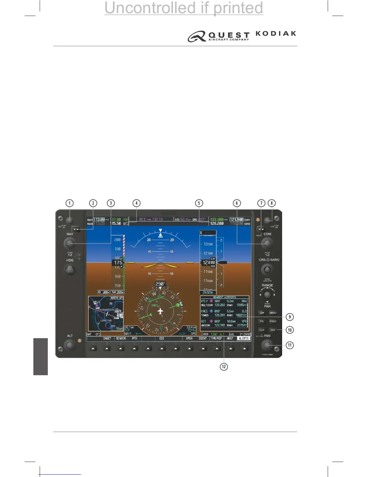
1. NAV VOL/ID Knob
2. NAV Frequency Transfer Key
3. NAV Knob
4. NAV Frequency Box
5. COM Frequency Box
6. COM Knob
7. COM Frequency Transfer Key
8. COM VOL/SQ Knob
9. Nearest Airports Window
10. ENT Key
11. FMS Knob
12. Transponder Data Box
 Loading...