SEAT REMOVAL AND INSTALLATION
Tools Required to Remove the Passenger and Crew Seats
The passenger and crew seats can be removed using the following tool(s):
a. Standard Flat Head Screw Driver (Passenger Seats)
b. Standard Phillips Head Screw Driver (Crew Seats)
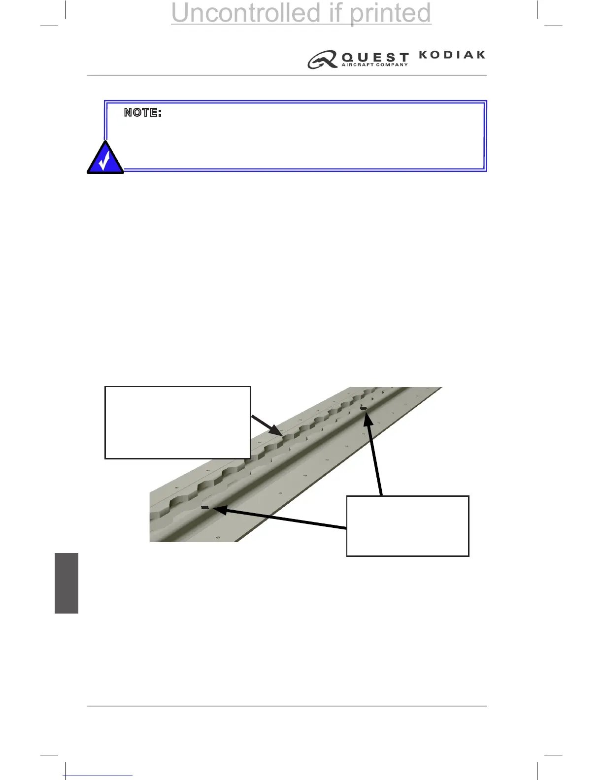
Seat Tracks
If equipped, seat tracks are marked with station identication markings every
10 inches, starting at FS (Fuselage Station) 50.0. These markings will assist
the operator in quickly installing seats. Refer to the following example of how
to properly install a seat.
Example: To install a seat in Row 3 (FS 115.0), locate fuselage station
marking FS 110.0 and count 5 seat track notches AFT. Insert the seat lock
paw into FS 115.0 and move the seat 1/2 inch AFT and engage the seat track
lock. This is the location for the center of the seats track lock pin.
Figure 7-57 – Seat Track Marking Example
For weight and balance calculations, the individual seat weights and seat CG
locations are provided in “Section 6” of this manual.
NOTE: The Passenger and Crew Seat installation and removal
instructions contained in this section can be performed by a pilot without
a logbook entry. If any seats are removed, a weight and balance for ight
must be calculated using the procedures dened in “Section 6” of this
manual.
 Loading...