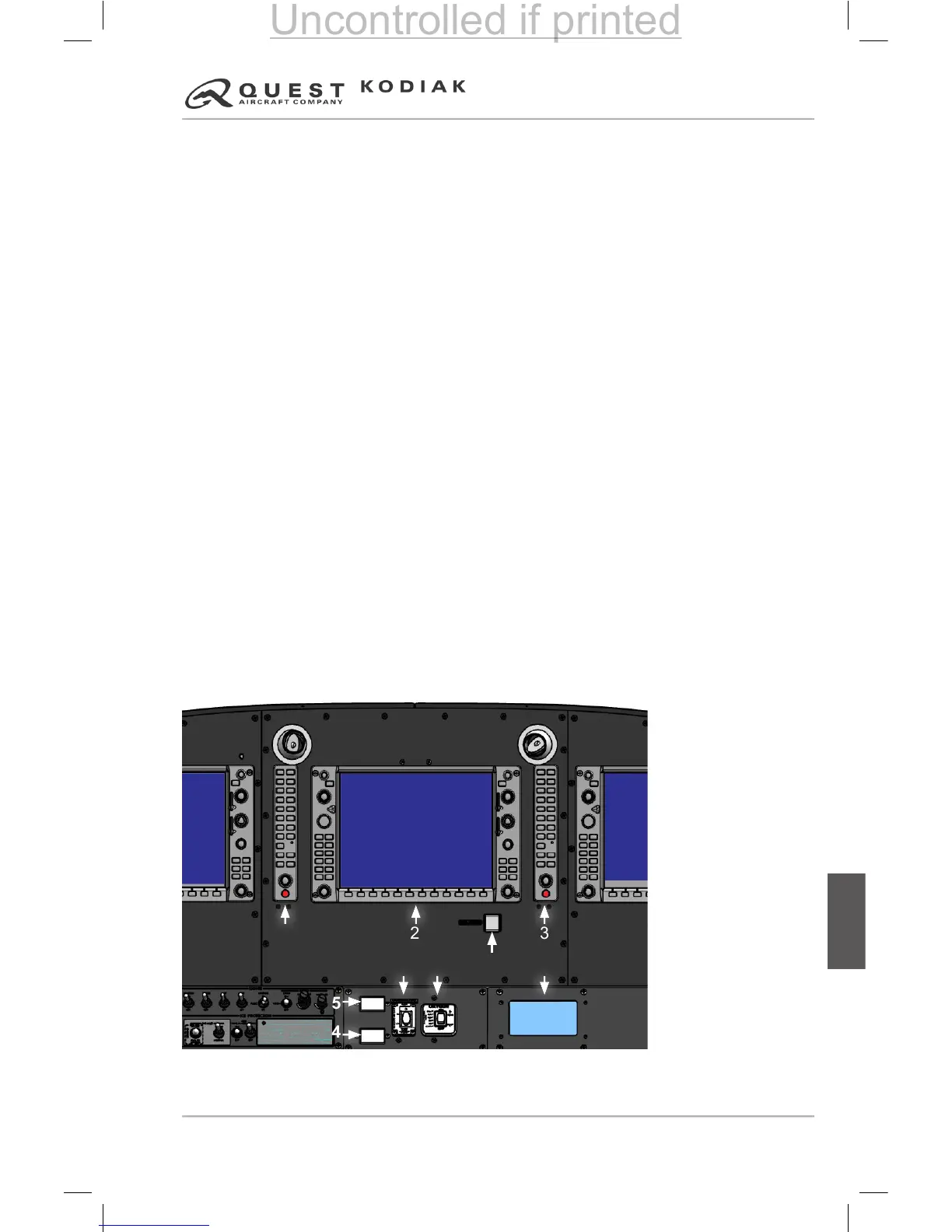
CENTER PANEL LAYOUT
The GDU 1040 Multifunction Display (MFD) is located on the center
instrument panel. The MFD depicts Engine Indication System information
along the left portion of the display and shows navigation, terrain, weather,
lightning and trafc data on the moving map. Flight management or display
conguration information can be shown on the MFD in place of the moving
map pages. Refer to the Garmin G1000 Pilot’s Guide (190-00590-XX) for
operating information.
The center panel contains two GMA 1347 audio panels (one installed on each
side of the MFD). A red push button switch labeled “DISPLAY BACKUP” to
manually select display reversion mode is located on the lower portion of the
GMA 1347. Refer to the GMA 1347 Pilot’s Guide for operating information.
The Emergency Locator Transmitter (ELT) mode switch (ON/ARM) is
located on the lower center instrument panel beneath the MFD. Refer to
the Emergency Locator Transmitter description in this section for operating
information.
The Flight Time (or Flight) and Block Time (or Engine) Hobbs Meters are
located to the left of the ELT mode switch. The Block Time (or Engine) Hobbs
Meter records the hours of engine use, and is activated by an oil pressure
switch in the engine compartment. The Flight Time (or Flight) Hobbs Meter
records the hours of ight time. The meter is activated by an airspeed switch
located forward of the instrument panel behind the lower left portion of the
MFD.
The oxygen supply pressure gage and oxygen system switch are located to
the right of the Hobbs Meters. For operating information regarding the oxygen
system refer to the Oxygen System description contained in this section of the
handbook.
1. Left Audio Panel
(GMA 1347)
2. MFD (GDU 1040)
3. Right Audio Panel
(GMA 1347)
4. Block Time (or
Engine) Hobbs
Meter
5. Flight Time (or
Flight) Hobbs Meter
6. ELT Switch
7. Oxygen Control
Panel
8. ECS Control Panel
9. TAWS Inhibit Switch
Figure 7-3 – Center Panel Layout
2 3
6 7
8
1
5
4
9
 Loading...