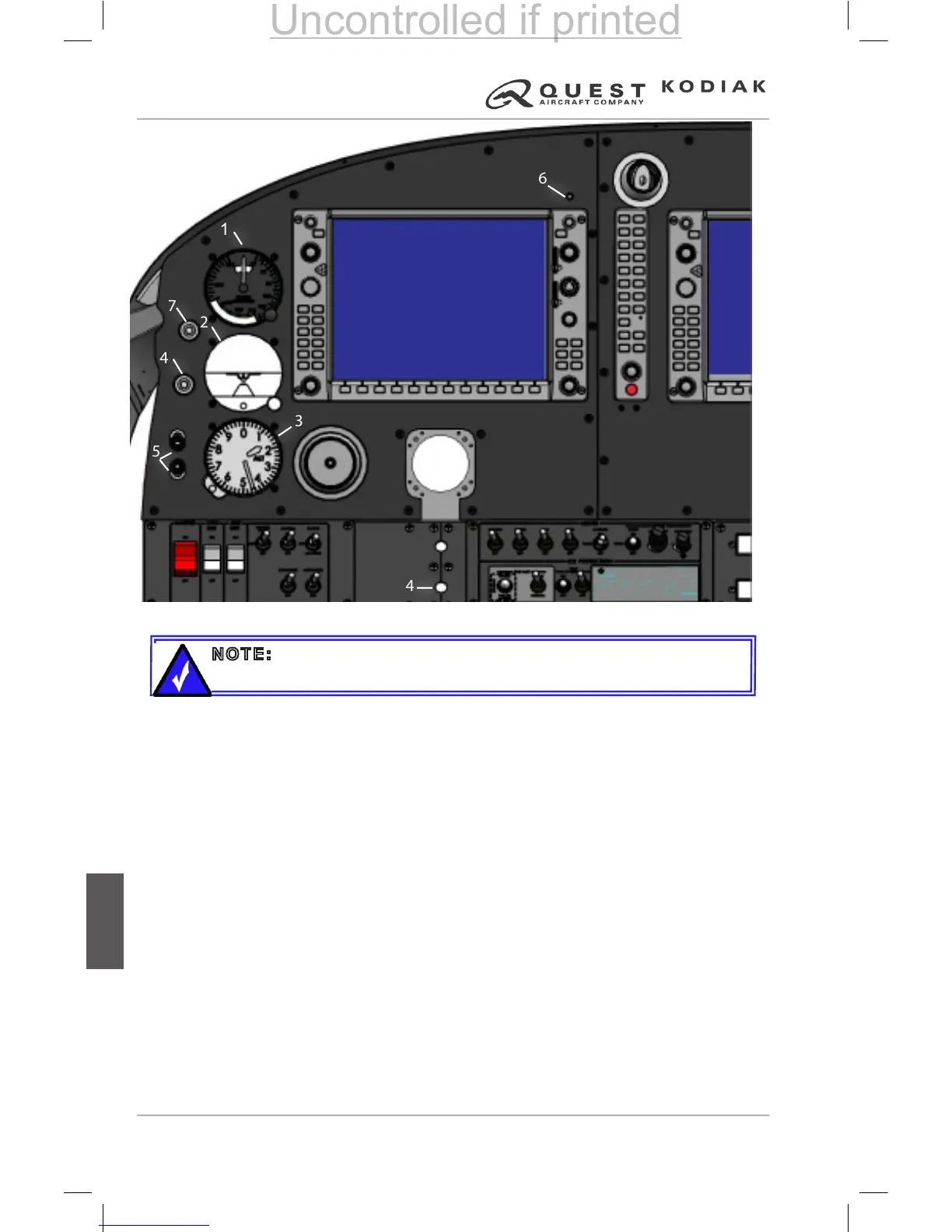
Figure 7-2 – Left Panel Layout
1. Standby Airspeed Indicator
2. Standby Attitude Indicator
3. Standby Altimeter
4. Overspeed Governor Test Button
5. Pilot’s Headset Jacks
6. Battery Master Switch
7. Avionics Bus Switch
8. Auxiliary Bus Switch
9. Auxiliary Fuel Pump Switch
10. Ignition Switch
11. Starter Switch
12. Generator Switch
13. Alternator Switch
14. Parking Brake Handle
15. Flashing Beacon Switch
16. Strobe Lights Switch
17. Navigation Lights Switch
18. Taxi Pulse Light Switch (if LED)
Taxi Light Switch (if incandescent)
19. Landing Lights Switch
or
Landing / Pulse Lights Switch
(if pulsing type)
20. Cabin Lights Switch
21. Instrument Panel Lighting
Rheostat (Dual)
22. Switch / Circuit Breaker Panel
Lighting Rheostat
23. Engine Inlet Inertial Separator
Switch
24. Left Pitot Heat Switch
25. Right Pitot Heat Switch
26. Fuel Selectors OFF Warning
Light
27. Stall Test Switch
28. Engine Inlet Override
1
2
26
3
6 7 8
9 10 11
12 13
15 16 17 18 19 20 21 22
23 24
25
14
4
5
27
28
NOTE: Panel represents only aircraft equipped with the Dual
Actuated Inertial Particle Separator System (DIPS).
 Loading...