POROUS PANELS
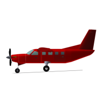
The KODIAK TKS Ice Protection System is a system that exudes a lmy ice
protection uid from porous panels on the leading edges of the aircraft. The
uid minimizes ice formation on all lifting surfaces, propeller blades, wings,
wing struts, and horizontal and vertical stabilizers. When the system is
activated in ight, the ice protection uid ows back over the upper and lower
surfaces of the area being protected and protects the leading edges from ice
build-up.
PROPELLER PROTECTION
A uid slinger on the propeller provides ice protection for the propeller and
generates further ice protection for the fuselage and cargo pod forward
surfaces. Two positive displacement, constant volume metering pumps
supply uid to the panels and propeller. Single and combined pump
operation and timed pumping provide a range of ow rates for varied icing
conditions. A single pump supplies TKS uid to the windshield spray nozzles
for clear visibility through the windshield.
WINDSHIELD SPRAYERS AND PUMP
The TKS Ice Protection System includes windshield protection through the
installation of windshield sprayers located at the base of the left windshield.
Ice protection uid is supplied to the sprayers by an on-demand gear
pump which is installed beneath the oor between the main landing gear
cross tubes. When the momentary spring loaded WINDSHIELD Switch
is activated, the pump runs for 4 seconds. In addition to providing ow for
windshield ice protection, the pump also acts as a priming pump for the
main metering pumps. In the event of a loss of system prime, the windshield
pump may be activated to purge the system of any air between the main
metering pumps and the uid reservoir. See the “Handling, Service &
Maintenance” section of this supplement for more information.
RESERVOIR
The uid reservoir for the known icing system has a total capacity of 16.0
gallons.
For the Console Reservoir conguration, the uid reservoir is located in the
center console between the two crew seats. The ller port for the Console
Reservoir is located on top of the center console and is accessed by lifting
the armrest.
For the Cargo Compartment Reservoir conguration, the uid reservoir
is located in the forward end of the forward bay of the External Cargo
Compartment and is accessed by opening the forward bay access door,
extending the exible ller tube, and removing the ller cap.

 Loading...