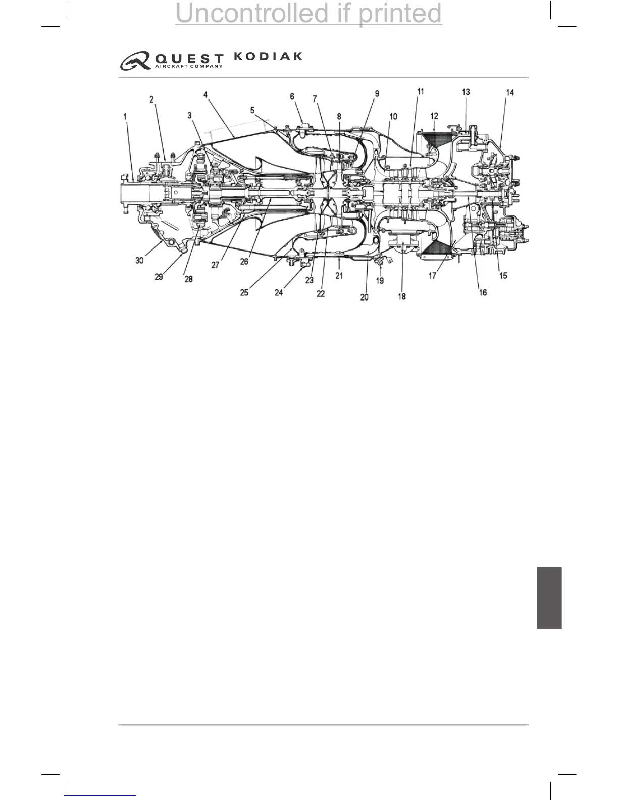
EasyManuals Logo

Kodiak 100 Series User Manual

Kodiak 100 Series
606 pages
To Next Page IconTo Next Page
To Previous Page IconTo Previous Page
Page #315 background imageLoading...
Page #315 background image
Pilot’s Operating Handbook
7-75
DO NOT USE FOR FLIGHT OPERATIONS
Section 7
AIRPLANE & SYSTEMS DESCRIPTIONS
100 SERIES
Systems
1. Propeller Shaft
2. Propeller Governor Mounting Pad
3. First-Stage Reduction Gear
4. Exhaust Duct
5. ITT Wiring Harness
6. Fuel Nozzle
7. ITT Bus-Bar and Probe Assembly
8. Compressor Turbine
9. Compressor Turbine Vane Ring
10. Centrifugal Compressor Impeller
11. Axial-Flow Compressor Impellers (3)
12. Compressor Air Inlet
13. Compressor Inlet Case
14. Accessory Gearbox
15. Accessory Gearbox Driveshaft
Figure 7-59 – PT6 Engine Diagram
16. Gearbox Coupling Shaft
17. Integral Oil Tank
18. Compressor Bleed Valve
19. Fuel Drain Valve
20. Diffuser Tube
21. Gas Generator Case
22. Power Turbine Vane Ring
23. Power Turbine
24. Flow Divider & Dump Valve
25. Combustion Chamber Liner
26. Power Turbine Shaft
27. Power Turbine Shaft Housing
28. Second-Stage Reduction Gear
29. Magnetic Chip Detector
30. Propeller Reduction Gearbox
Uncontrolled if printed

Table of Contents

Questions and Answers:

Question and Answer IconNeed help?

Do you have a question about the Kodiak 100 Series and is the answer not in the manual?

Kodiak 100 Series Specifications

General IconGeneral
ManufacturerDaher
EnginePratt & Whitney Canada PT6A-34
Service Ceiling25, 000 feet
Seating Capacity10
Crew1-2
Range1, 132 nautical miles
TypeUtility aircraft
Length34 feet 2 inches
Wingspan45 feet
Max takeoff weight7, 255 pounds
Power Output750 shp
Cabin Width4 feet 6 inches