nose down. The airspeed switch activates the automatic trim system at
approximately 35 knots. For maintenance/ground testing of the automatic trim
system, a push to test button is provided. The push-to-test button bypasses
the airspeed switch and allows the automatic trim system to function on the
ground. The push to test button is located on the ap/trim compensation unit
inside the control pedestal.
The automatic trim system operates the elevator trim tab through a range of
7° nose-up trim to full nose-down trim tab deection (15°). The aircraft does
not require any trim compensation with varying ap position beyond this range
of elevator trim tab travel. Disabling of the automatic trim system between 7°
nose-up and full nose-up is accomplished through a voltage comparator in the
ap/trim compensation unit which monitors the trim tab position though the
potentiometer which provides elevator trim position to the G1000.
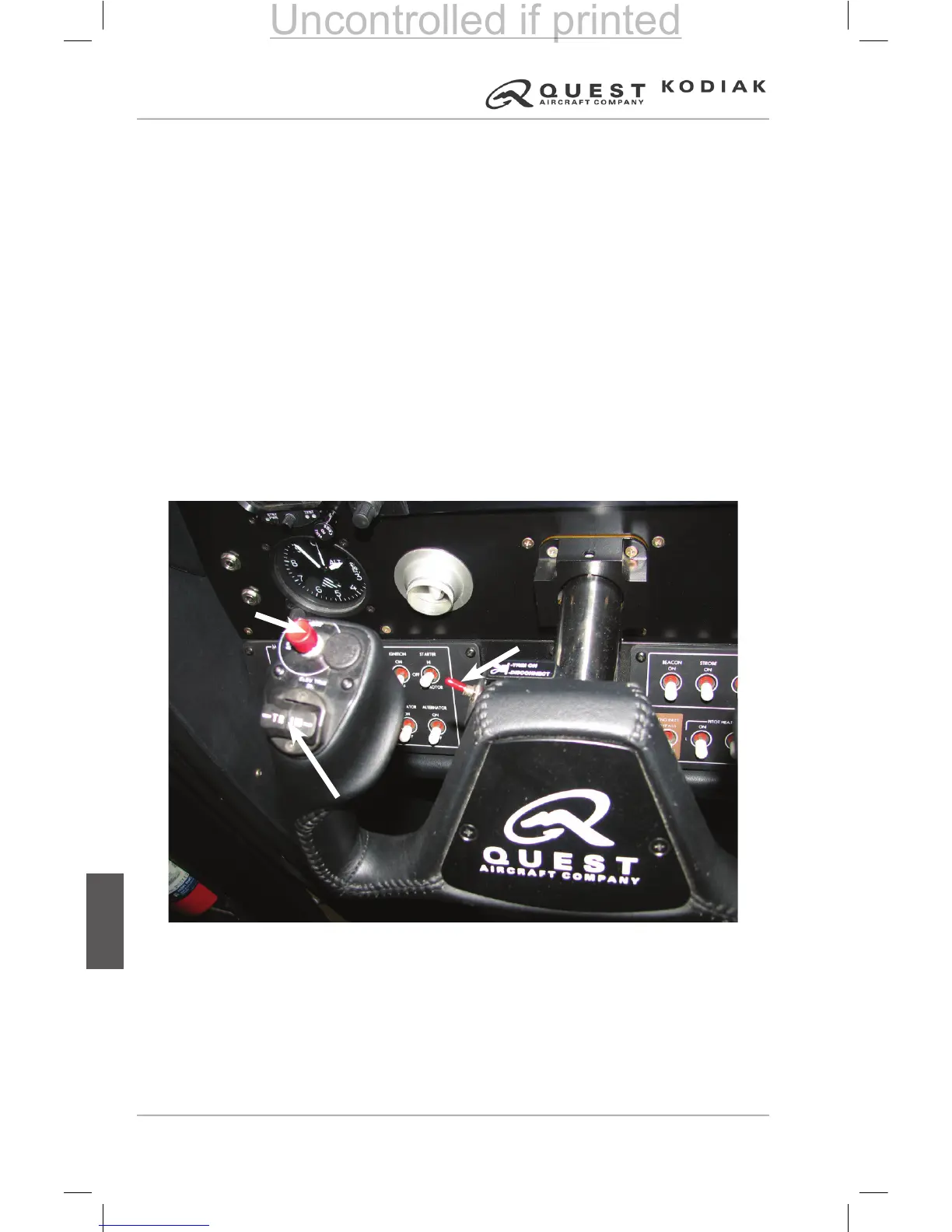
As with any electric trim system, a trim disconnect switch is provided for
disabling all trim systems on the aircraft (including the automatic trim system
and autopilot). If a trim runaway condition occurs, move the trim disconnect
switch to the DISCONNECT position (aft). The airplane may then be
retrimmed using the manual trim wheel located on the control pedestal.
Figure 7-86 – Autopilot and Trim Disconnect Switches
Electronic Pitch
Trim Dual Switch
Autopilot Disconnect
Switch
Trim Disconnect
Switch
 Loading...