Maintenance 16
Servicing the main gearbox 16.7
Comprima V 180
Original Operating Instructions 150001053_00_en 173
16.7 Servicing the main gearbox
RPG000-089
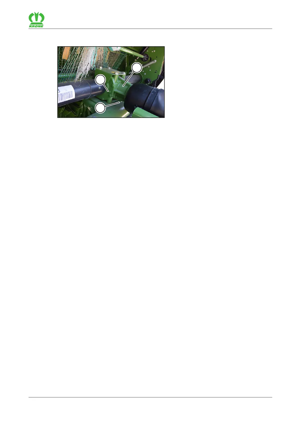
The main gearbox(1) is located behind the drawbar in the front area of the machine. The
locking screw of the inspection and filling hole(3) is located on the side of the main gearbox.
The locking screw(2) for the oil drain is located on the underside of the main gearbox(1).
Maintenance intervals: refer to page160
Amount and type specifications of the oil: refer to page41
ü The machine is horizontal on stable and level ground.
ü The machine is shut down and safeguarded, refer to page25.
Checking oil level
Remove the locking screw from the inspection and filling hole(3).
ð The oil must reach the inspection and filling hole(3).
If the oil reaches the inspection and filling hole(3):
Screw the locking screw into the inspection and filling hole(3), tightening torque refer to
page169.
If the oil does not reach the inspection and filling hole(3):
Top up with fresh oil via the inspection and filling hole(3) up to the inspection and filling
hole(3).
Screw the locking screw into the inspection and filling hole(3), tightening torque refer to
page169.
Changing the oil
ü A suitable container is available for escaping oil.
Remove the locking screw from the inspection and filling hole(3).
Remove the locking screw(2) from the oil drain.
Collect the oil in a container.
Screw in the locking screw(2), refer to page169.
Pour in fresh oil via the inspection and filling hole(3) up to the inspection and filling hole(3).
Screw the locking screw into the inspection and filling hole(3), tightening torque refer to
page169.