Initial operation 6
Universal shaft 6.6
Comprima V 180
Original Operating Instructions 150001053_00_en 49
ü The universal shaft chain and the chain holder have been removed.
Take the universal shaft bracket(1) out of the storage compartment.
To mount the universal shaft bracket(1), remove the screw connection(3) and clamp the
universal shaft bracket(1) on the drawbar.
Mount the screw connection(3).
Æ The universal shaft(2) can be deposited with the bottom hitching of the drawbar on the
universal shaft bracket(1), refer to page142.
6.6.4 Mounting the universal shaft on the machine
WARNING
Risk of injury by failure to take account of the danger zone of the universal shaft
If the danger zone of the universal shaft is ignored, persons can be seriously hurt or killed.
To avoid accidents, observe the danger zone of the universal shaft, refer to page18.
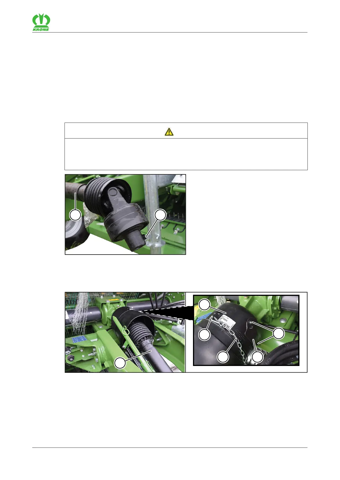
RP000-281
ü The machine is shut down and safeguarded, refer to page25.
ü The protective cap is mounted, refer to page48.
Remove the screw connection(2) from the universal shaft(1).
RP000-282
To facilitate access to the screw connection(2) on the universal shaft(1), remove the screw
connections(7) and the cover(6) on the protective cap(3).
Push the universal shaft(1) onto the PTO shaft end of the machine.
Mount the screw connection(2) through the resulting hole behind the cover(6).
Mount the cover(6).
Hook the universal shaft chain(5) into the eye(4) on the protective cap(3).