Terminal menus 13
Menu 15 "Settings" 13.20
Comprima V 180
Original Operating Instructions 150001053_00_en 135
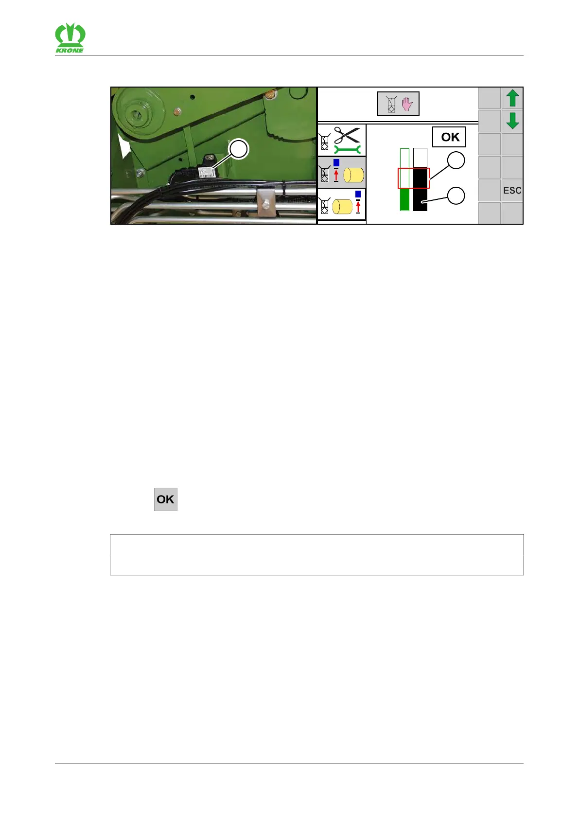
13.20.1.1 Adjusting sensor B09/B10 “Filling display left/right”
1
state:
15-1
2,4V
1,9V
3,2V1,9V
1
2
EQG003-042
The sensor(3) is located behind the side hood:
• B09 on the left side of the machine
• B10 on the right side of the machine
The green bar in menu 15-1 “Sensor test” shows the saved value. The black bar shows the
current value of the sensor. As soon as a new value is saved, the green bar is adjusted to the
black one.
ü The bale chamber is closed and empty.
ü The density of the bale core is set in positionIII – “Low density of the bale core”, see
operating instructions, chapter Operation, “Adjusting the density of the bale core”.
ü Menu 15-1 “Sensor test” is open.
ü SensorB09 or B10 has been selected.
If the bar(2) is not inside the rectangle(1) when the bale chamber is closed and empty, adjust
the sensorB09 or B10 mechanically:
Loosen the screw connections of the sensor and move them in the oblong hole until the
bar(2) on the display is inside the rectangle(1) of the bargraph.
ð An acoustic signal sounds when the bar(2) is inside the rectangle(1).
Tighten the screw connections of the sensor.
Press .
Æ The set position is saved.
INFORMATION
Saving is only possible if the bar (2) is inside the rectangle (1) of the bargraph.
13.20.1.2 Adjusting sensor B61 “Tying 1 (passive)”
The following positions are saved with sensorB61 “Tying 1 (passive)”:
• The feed position,
• the cutting position and
• the tying position.