Appendix 21
Hydraulic diagram 21.1
Comprima V 180
Original Operating Instructions 150001053_00_en 231
21 Appendix
21.1 Hydraulic diagram
Legend for the following hydraulic diagram
1 Standard equipment 3 For version with "Hydraulic support
jack"
2 For version with "Electronic baling
pressure adjustment"
4 "Reversing device" version
List of the actuators and icons for the following hydraulic diagram
For an overview of the location of the sensors, refer to page170.
A list of the sensors, actuators and control units is provided in the circuit diagram, refer to
page231.
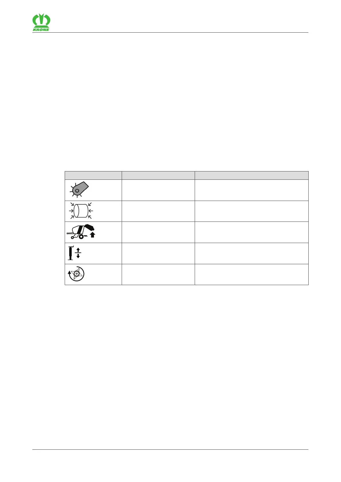
Icon Actuator Explanation
– Pick-up
Q30 Baling pressure (for the “Electronic baling
pressure adjustment” version)
– Tailgate on the bale chamber
– Hydraulic support jack
– Reversing device
Documents about this
2 150102247_00 Comprima V (Resources/pdf/3071044363.pdf)
21.2 Circuit diagram
Documents about this
2 150 100 117 02 (Resources/pdf/3071543819.pdf)
2 150 102 131 01 (Resources/pdf/3071536651.pdf)