16 Maintenance
16.17 Adjust drive chains
182
Comprima V 180
Original Operating Instructions 150001053_00_en
The dimensionX
1
andX
2
of the tensioned spring length must be X
1
=60mm and X
2
=60mm.
ü The machine is shut down and safeguarded, refer to page25.
ü The pick-up is lowered to working position, refer to page75.
ü The pick-up guard on the right side of the machine has been removed.
ü The drive chains(1) and (2) and the pick-up guard have been cleaned.
To increase the chain tension, turn nut(4) and(5) clockwise until the dimension X
1
=60mm
and X
2
=60mm has been set.
To reduce the chain tension, turn nut(4) and(5) anti-clockwise until the dimension
X
1
=60mm and X
2
=60mm has been set.
INFORMATION
The drive chain is supplied with oil via the central chain lubrication system, refer to page91.
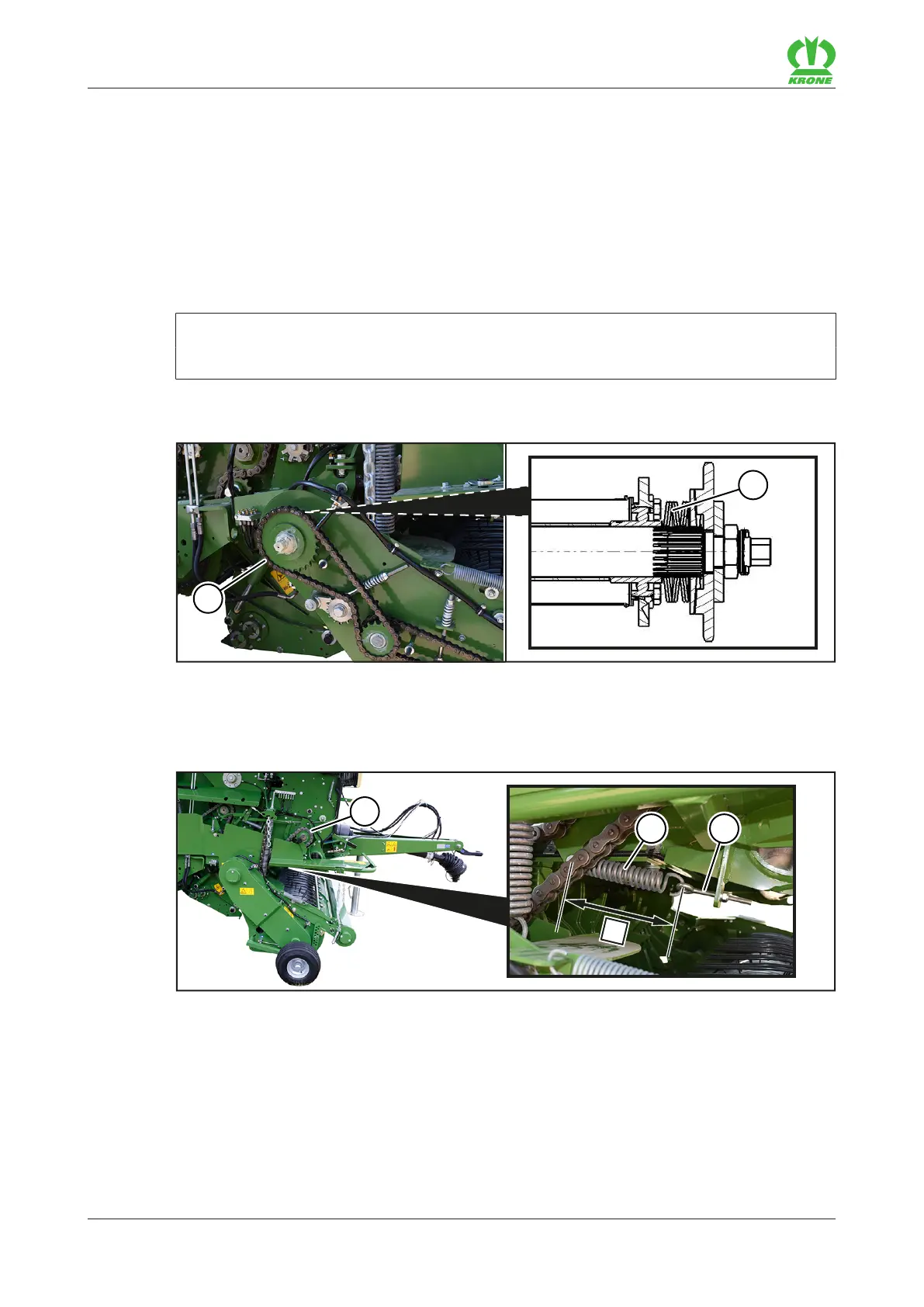
Spring discs of the pick-up drive
RP000-472
After repairing the pick-up drive(1), ensure that the disc springs(2) are arranged as shown.
16.17.2 Drive chain of the intake
RP000-471
The drive chain(1) of the intake (starter rollers/feed roller) is located on the right side of the
machine.
The dimensionX of the tensioned spring length(2) must be X=200mm.
ü The machine is shut down and safeguarded, refer to page25.
ü The right side hood is open.
To tension the drive chain(1), use the nut on the eyelet bolt(3) to set the
dimensionX=200mm.