6 Initial operation
6.7 Mounting the bale ejector
50
Comprima V 180
Original Operating Instructions 150001053_00_en
INFORMATION
For more details or in case of different universal shafts, refer to the operating instructions for
the universal shaft comprised in the delivery.
6.7 Mounting the bale ejector
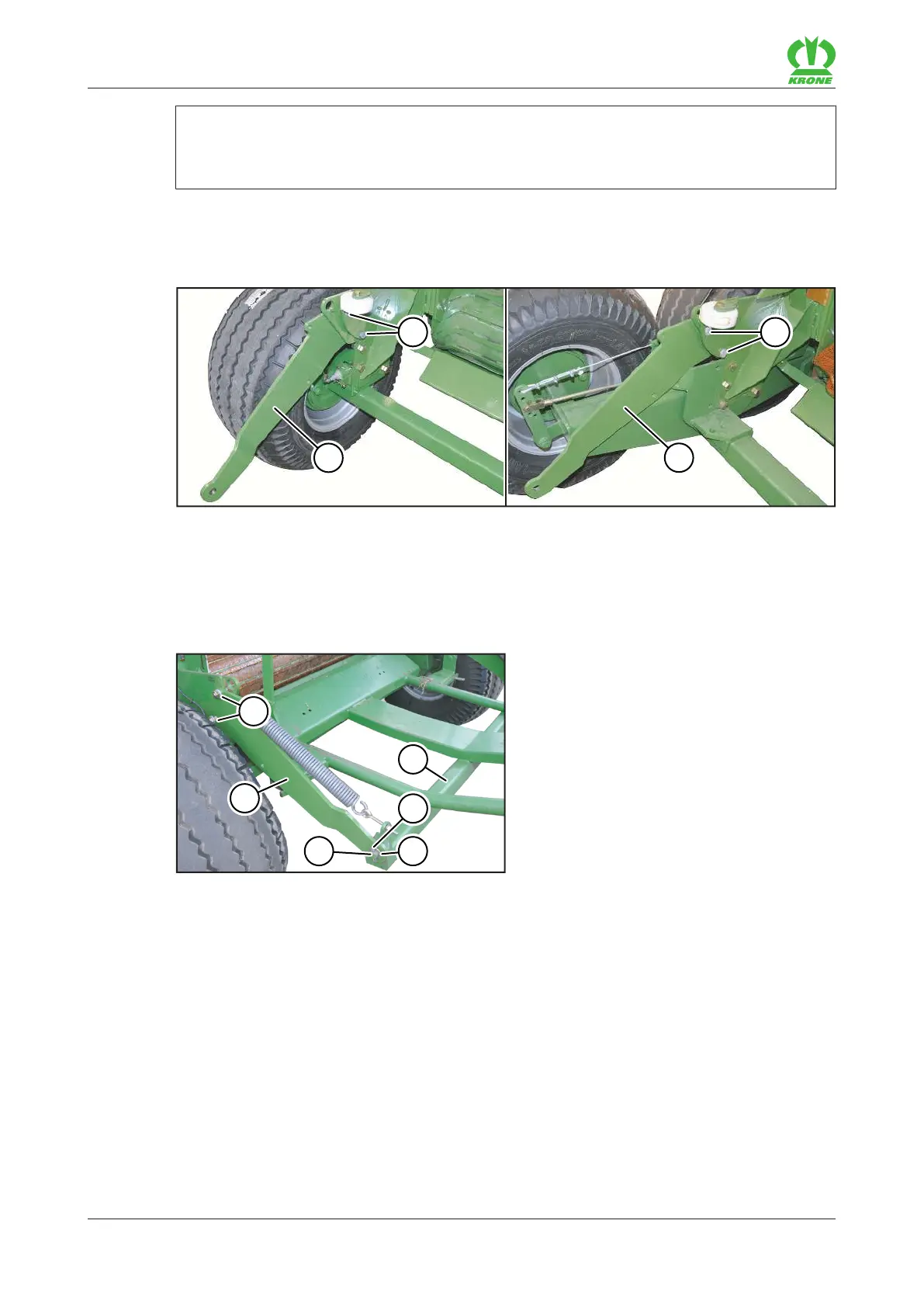
For "single axis" version For "Tandem axle" version
RP000-494
ü The tailgate is opened and secured, refer to page73.
ü The machine is shut down and safeguarded, refer to page25.
Undo the screw connections (1) on the mounting plates (2) on the right and left side, but do
not remove.
Fold the mounting plates (2) outwards.
RP000-495
Slide the bale ejector (2) between the mounting plates (6), inserting the bolts (5) into the
lower bores on the mounting plates (6) on the right and left side of the bale ejector (2).
Secure the bolts (5) on the right and left of the bale ejector (2) with a disc (4) and clamping
sleeve (3).
Tighten the screw connections (1) of the mounting plates on the right and left side of the
bale ejector (2).