CertusPro-NX SerDes/PCS Usage Guide
Preliminary Technical Note
28 © 2020-2021 Lattice Semiconductor FPGA-TN-02245-0.81
All rights reserved. CONFIDENTIAL
For the signal mapping of this port, refer to Table 5.12.
For the signal mapping of this port, refer to Table 5.12.
For the signal mapping of this port, refer to Table 5.12.
For the signal mapping of this port, refer to Table 5.12.
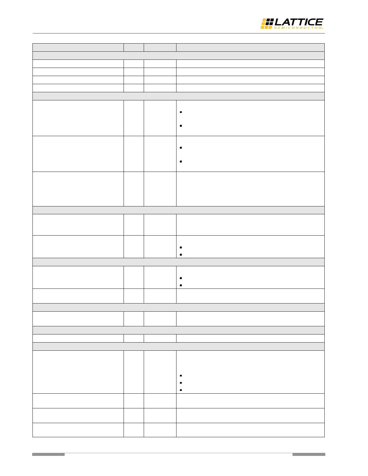
Elastic Buffer Signals (8B/10B PCS)
Elastic Buffer Empty output port.
1’b1 – the frequency compensation buffer, Elastic Buffer, is
empty.
1’b0 – the frequency compensation buffer, Elastic Buffer, is
not empty.
Elastic Buffer Full output port.
1’b1 – the frequency compensation buffer, Elastic Buffer, is
full.
1’b0 – the frequency compensation buffer, Elastic Buffer, is
not full.
In GigE application case, the high level of this signal indicates
the current state is GigE Auto-negotiation. In this state, replace
/C1/, /C2/ with /I2/ ordered sets periodically so that the
following stage (CTC) gets opportunity to perform clock
frequency compensation.
Word Aligner Signals (8B/10B PCS)
Word alignment enabling input port. This function is useful, if
the automatic synchronization is not enabled. The rising edge of
this signal triggers the word alignment operation.
Link Synchronization output port.
1’b1 – link synchronization is acquired.
1’b0 – loss of link synchronization.
Lane-to-Lane Deskew Signals (8B/10B PCS)
Receive Lane align output port.
1’b1 – alignment acquired.
1’b0 – loss of alignment.
Receive Deskew enable port. The rising edge of this signal
triggers the lane-to-lane deskew operation.
BER Monitor (64B/66B PCS)
The high level of this signal indicates the high bit error ratio is
indicated.
Block Aligner (64B/66B PCS)
The high level of this signal indicates the block lock is achieved.
PMA Control and Status Signals
This signal is used to put PMA in powerdown mode. This signal
has only three states. This signal is required to be clocked on
mpcs_clkin_i.
2’b11 – deep low-power state.
2’b10 – low-power state.
2’b00 – operational state.
This signal is used to load Electrical Idle III in the Tx driver of the
PMA macro.
This port is used to signal the Electrical Idle condition detected
by the PMA control logic. This signal is driven by mpcs_clkin_i.
This signal is used to report to PMA control logic that error data
is detected by the PCS logic. Asserting this signal leads CDR PLL
 Loading...