8.5.9 Modbus LED status displays
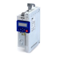
Informaon about the Modbus status can be obtained quickly via the "MOD-RUN" and "MOD-
ERR" LED displays on the front of the in
verter.
The meaning can be seen from the tables below.
Inverter not acve on the Modbus bus (yet)
LED display Meaning
(MOD-ERR is lit permanently)
Internal error
(MOD-RUN and MOD-ERR are ickering)
Automac baud rate
detecon
acve.
Inverter acve on the Modbus
The green "MOD-RUN" LED indicates the communicaon status:
LED display Communicaon status
O No recepon / no transmission
On Recepon / transmission acve
The red "MOD-ERR" LED indicates an error:
LED display Fault
O No fault
Blinking Communicaon error
8.5.10 Reset Modbus interface
Parameter Name / value range / [default seng] Info
0x2320
(PAR 508)
Acvate Modbus network
(Acv. ne
tw. se.)
0 ... [0] ... 1
1 = acvate network opons.
8.5.11 Modbus response me
Parameter Name / value range / [default seng] Info
0x2321:004
(PAR 510/004)
Modbus sengs: Minimum response me
(Modbus se.: Min. resp. me)
0 ... [0
] ... 1000 ms
Minimum me delay between the recepon of a valid message and the
response of the drive.
Conguring the network
Modbus
Modbus LED status display
s
136

 Loading...


