Crane operation
11.5 Crane operation with main boom
Operating manual 3 302 736 en 11 - 89
GMK4090
xx.xx.xxxx
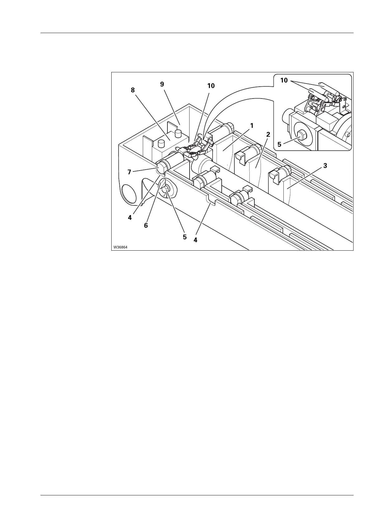
Overview This illustration shows the completely retracted main boom with the basic
section (9) and the first three telescopic sections
I to III (1) to (3).
Each telescopic section is equipped with two locking pins (7) which are
extended by spring force.
The locking pins (7) are pushed into the cutouts (4) of the telescopic section
above at the locking points – the telescopic section is locked.
The telescoping cylinder is attached to the basic section (9) with the piston
rod (8). The telescoping cylinder has two locking pins (5) at the bottom and
a mechanism at the top (10).
When the telescoping cylinder is positioned at a locking point:
– The locking pins (5) can be extended into the cutouts (6) – the telescoping
cylinder is locked.
– The mechanism (10) engages into the locking pins (7) and can retract
them – the telescopic section is unlocked.
s
 Loading...