Driving modes
6.4 Installing/removing the outrigger beams
6 - 28 3 302 736 en Operating manual
GMK4090
xx.xx.xxxx
6.4.10 Disconnecting/establishing the connections to the supporting
box
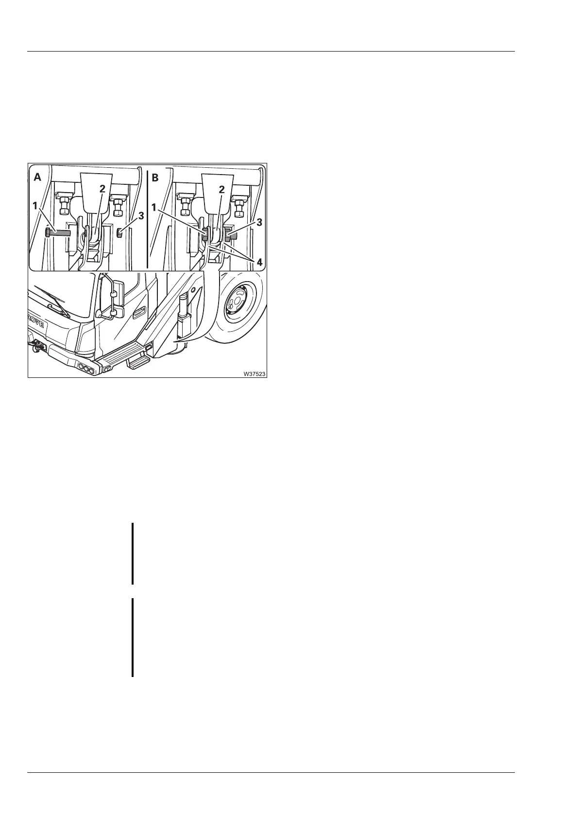
The illustrations show the connecting point for the front right outrigger
beam as an example.
(A) – Disconnecting the connection
• Remove the nut (3).
• Remove the bolt (1) from the connecting
point (2).
(B) – Establishing the connection
• Fasten the bolt (1) to the connecting point (2)
using the nut (3). Screw the nut only tightly
enough so that the attachment plates (4) still
have lateral play.
6.4.11 Pulling out/Inserting the outrigger beam
Extending the
outrigger beam
• Check that the outrigger beams are released and are secured between
each other;
à Preparations – for removal, p. 6 - 20.
S
Risk of damage to hydraulic lines!
Ensure that the hydraulic lines on the outrigger beam do not remain hang-
ing on the supporting box and become damaged.
G
Danger of overloading due to diagonal pull!
Always only pull the outrigger beams so far out of the supporting box (e.g.
using a chain hoist) so that you can sling them at their centre of gravity, and
then lift them out of the supporting box using the truck crane.
This prevents the truck crane becoming overloaded due to impermissible
diagonal pull.

 Loading...