© 2011 MIMAKI ENGINEERING CO.,LTD. 6.2.6 R.2.0 P.1
1
2
3
4
5
6
7
8
Maintenance Manual > Disassembly and Reassembly > Ink-related Parts > Cartridge Guide Assy.
Model UJF-3042/FX Issued 2010.08.27 Revised 2011.09.30 F/W ver --- Remark
2.0
6.2.6 Cartridge Guide Assy.
Procedures
1. Turn the main power OFF.
2. Remove the Cartridge Cover and the Rear Cover.
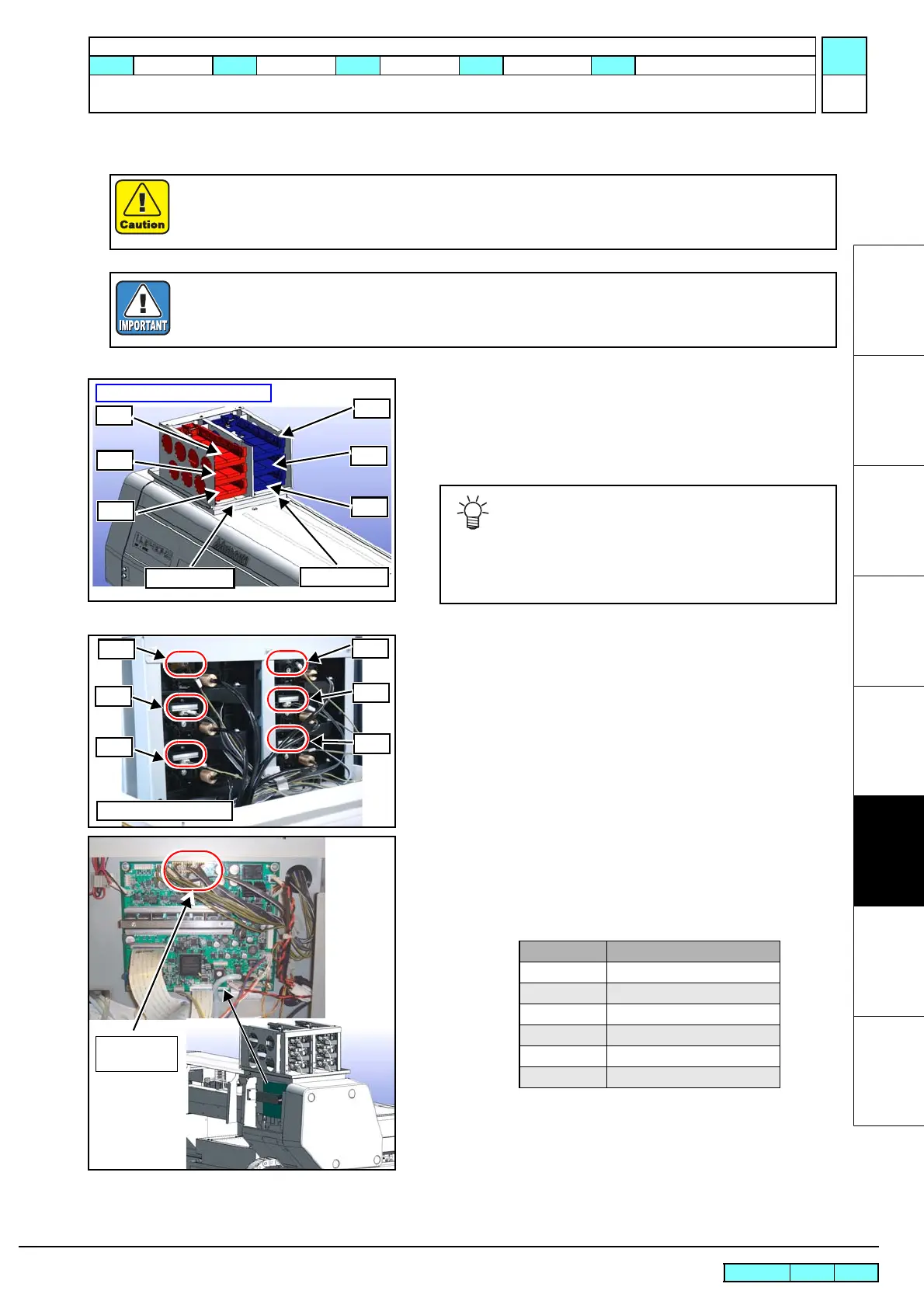
3. Check the slots.
4. Disconnect all connectors(cable) from the ID Contact PCB.
5. Remove the Cartridge Sensor Assy from the Slider Relay PCB,
and draw the cable to the back of the Cartridge Guide Assy.
See the following table for connector numbers and cartridge
numbers of the Slider Relay PCB board.
To turn power off, be sure to turn the main power OFF.
Be sure to wear Protective Glasses and Working Gloves during the work operation.Ink may get in
your eyes depending on the working condition, or hand skin may get rough if you touch the ink.
Be sure to start the work after confirming the working process.
(Refer to “3.1.4 Replacement of Cartridge Guide Assy.”)
Take care not soil the surroundings.
Numbers indicate the color order
Group 1
Group 2
1
3
5
2
4
6
The Cartridge Guide Assy consists of two groups of
cartridge guides, and each group contains three car-
tridge guides arranged one on top of the other.
Assembly/disassembly is performed by group. Check
the position of the target cartridge before disassem-
bling.
ID Contact PCB (x6)
1
2
3
4
5
6
CN No. Cartridge No.
CN10 Cartridge 1
CN11 Cartridge 2
CN12 Cartridge 3
CN14 Cartridge 4
CN15 Cartridge 5
CN16 Cartridge 6

 Loading...


