© 2011 MIMAKI ENGINEERING CO.,LTD. 4.2.17 R.2.0 P.1
1
2
3
4
5
6
7
8
R.1.1
Maintenance Manual > Adjustment > Adjustment Items > Head Voltage Adjustment
Model UJF-3042/FX Issued 2010.08.27 Revised 2011.09.30 F/W ver 1.80 / 1.00 Remark
2.0
4.2.17 Head Voltage Adjustment
Outline
This section describes the head voltage adjustment which is performed when the ink discharge becomes unstable and
the deflection of ink drop flight path occurs. As an adjusted value, an offset value for the head-specific reference volt-
age is set.
If this adjustment does not improve the situation, the head needs to be replaced.
Check
1. Set the media in the table.
2. Select [#ADJUST] -> [HEAD VOLT ADJ].
3. Select “CHECK” for [SELECT].
4. Press [ENTER] and print a pattern.
[ENTER]: Starts printing a pattern.
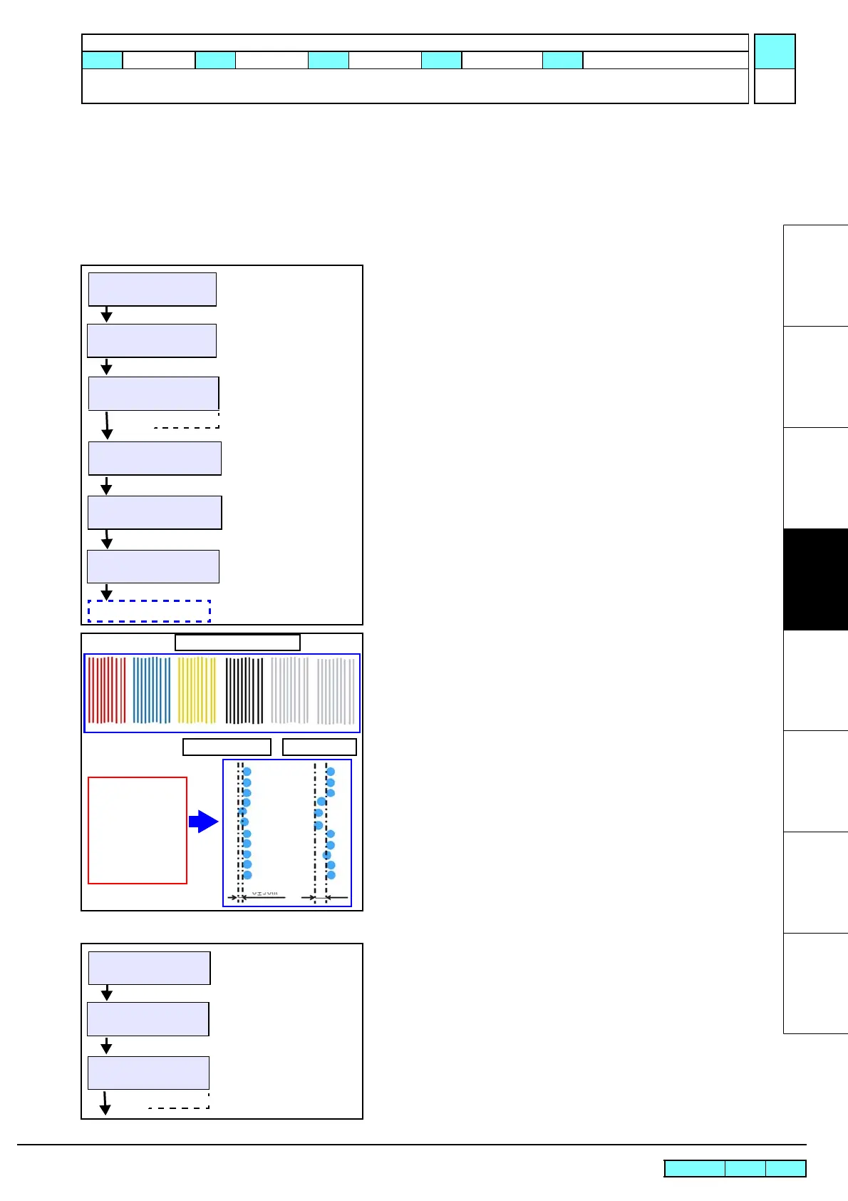
5. Check the pattern.
Enlarge a single shot line from nozzle row of each color and
check the dots in the line.
If the deviation of each dot in Y direction is within the follow-
ing range, the color (nozzle row) is considered acceptable.
“0 ±30 um
If the deviation is big as shown in “Bad example” in the left fig-
ure, perform the voltage adjustment described below.
Work Procedures
6. Select [#ADJUST] -> [HEAD VOLT ADJ].
7. Select “ADJUST” for [SELECT], and Press [ENTER] key.
FUNCTION
#ADJUST <ent>
#HEAD VOLT ADJUST
SELECT :CHECK
#HEAD VOLT ADJUST
PRINTING
ADJUST
#HEAD VOLT ADJUST
PRINT START :ent
HEAD TEMP. CONTROL
PLEASE WAIT
Patern Drawing
#ADJUST
HEAD VOLT ADJ <ent>
Good example
Single shot from one
nozzle row
Acceptable deviation
of each dot in the same
nozzle row:
“0
±
30 um”
0~30um
Check Patern (all color)
Bad example
FUNCTION
#ADJUST <ent>
#ADJUST
HEAD VOLT ADJ <ent>
#HEAD VOLT ADJUST
SELECT :ADJUST
CHECK

 Loading...


