© 2011 MIMAKI ENGINEERING CO.,LTD. 4.2.2 R.2.0 P.4
4.2.2 HEAD ADJUST
1
2
3
4
5
6
7
8
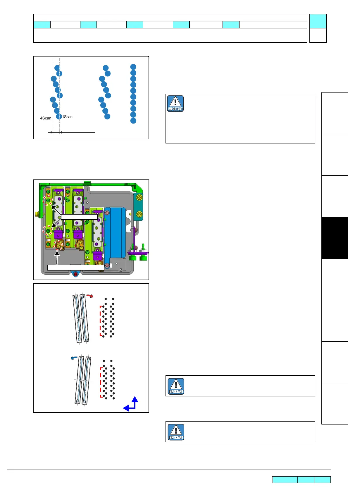
9. Check if no displacement occurs between the 1st scanning and
the 4nd scanning of the head.
*If the adjustment is required, execute the Procedures of Head
Slant Adjustment Adjusting Procedure (p.4).
Procedures of Head Slant Adjustment Adjusting Procedure
1. Loosen the slant fixing screw of the target head.
2. Rotate the slant adjustment screw according to the amount of
displacement to adjust the slant.
Rough indication of turning angle: About 2.5 µm by one-eighth
rotation
Direction of turning the Micro Adjuster
To correct slanting left: Turn counterclockwise (CCW).
To correct slanting right: Turn clockwise (CW).
3. Tighten the loosened slant fixing screw.
4. Redraw Patterns and check if there is no slanting.
Check patterns on all heads (1-8).
(Execute for all heads even when one head is
replaced.)
If there is no displacement, execute “Procedures
of Head Back/Forth Adjustment (p.7)” succes-
sively.
Slant fixing screw
Head slant adjustment screw
Y (+)
X (+)
Overlapped portion
To correct slanting left: CCW
Overlapped portion
To correct slanting right: CW
Tighten the screws with care that the head is not
shifted from the correct position.
Repeat “Adjusting” -> “Patterns Drawing” until no
more displacement is available.
Maintenance Manual > Adjustment > Adjustment Items > HEAD ADJUST
Model UJF-3042/FX Issued 2010.08.27 Revised 2011.09.30 F/W ver 1.80 / 1.00 Remark
2.0

 Loading...


