Chapter Three: Overview Inside the T
e 146 Unit
67
Auxiliary Output Board
The Auxiliary Output board contains relays C and D (which supplement relays A and B), and
analog outputs 2 and 3. The modified, male 9-pin Type “D” connector at the top of the board
allows operation of 120 VAC devices. The 9-pin female Type “D” connector at the bottom of
the board carries relay status, analog output signals 2 and 3, and their return lines. Table 22 lists
the pin functions of the relay connections and Table 23 lists the functions for the analog outputs.
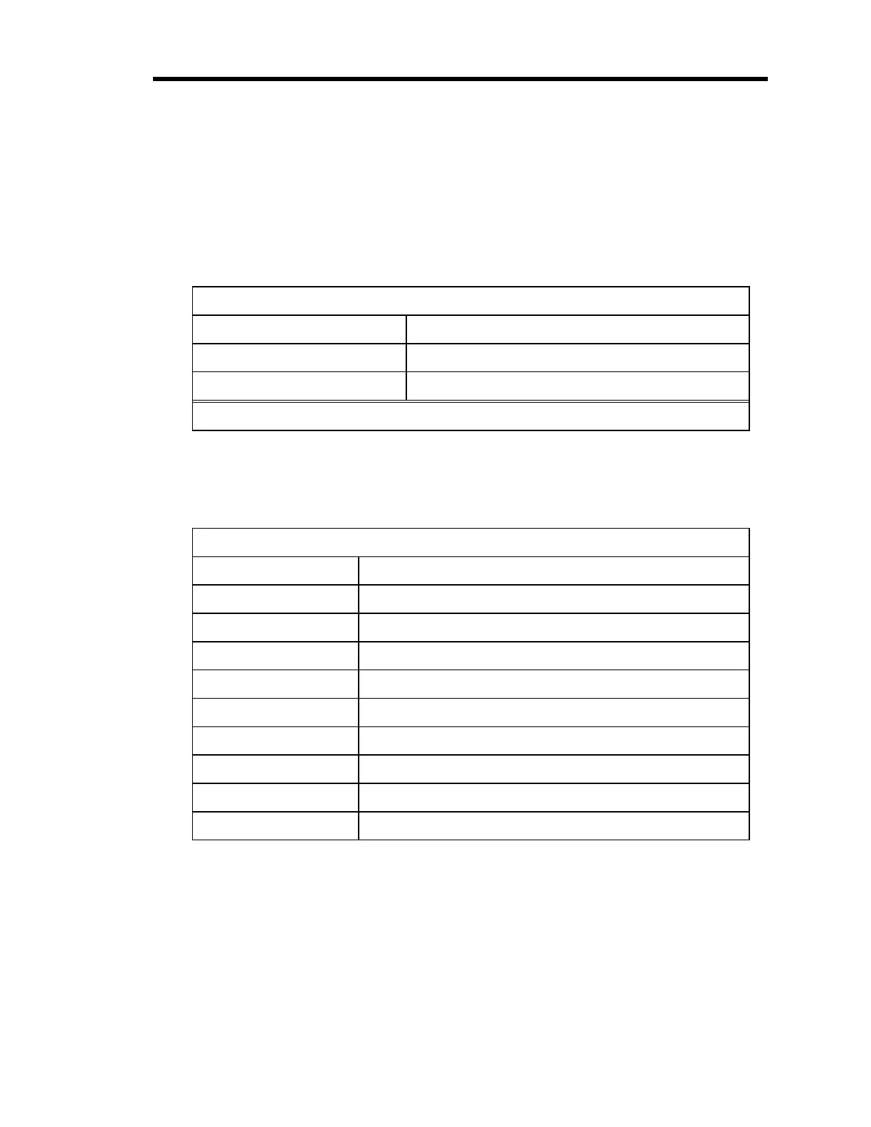
Relay Output (Top) Connector Pinout
Pin Number Assignment
1, 6, 2 Relay C (NO, C, NC)
*
4, 9, 5 Relay D (NO, C, NC)
*
*
NO = Normally Open, NC = Normally Closed, C = Common to both
Table 22: Relay Output (Top) Connector Pinout
Status/Analog Output (Bottom) Connector Pinout
Pin Number Assignment
1 Relay C Status (high = energized)
2 Relay D Status (high = energized)
3 Reserved
4 Reserved
5 Analog 2 Common (Signal Ground)
6 Analog 3 Out
7 Analog 3 Common (Signal Ground)
8 Analog 2 Out
9 Digital Ground
Table 23: Status/Analog Output (Bottom) Connector Pinout
Artisan Technology Group - Quality Instrumentation ... Guaranteed | (888) 88-SOURCE | www.artisantg.com