Chapter Three: Overview Inside the T
e 146 Unit
65
General I/O Connector
The General I/O connector is a 25-pin male Type “D” connector. This connector brings out the
analog output 1 signal, Relay A and B contacts, and remote zero, alarm latch, and front-panel-
lockout digital control lines. The front panel lockout feature provides a security measure to
prevent inadvertent command entry through the front panel. The front panel can also be locked
or unlocked via RS-232 communications. The Relay A and B contacts can handle up to 1A at
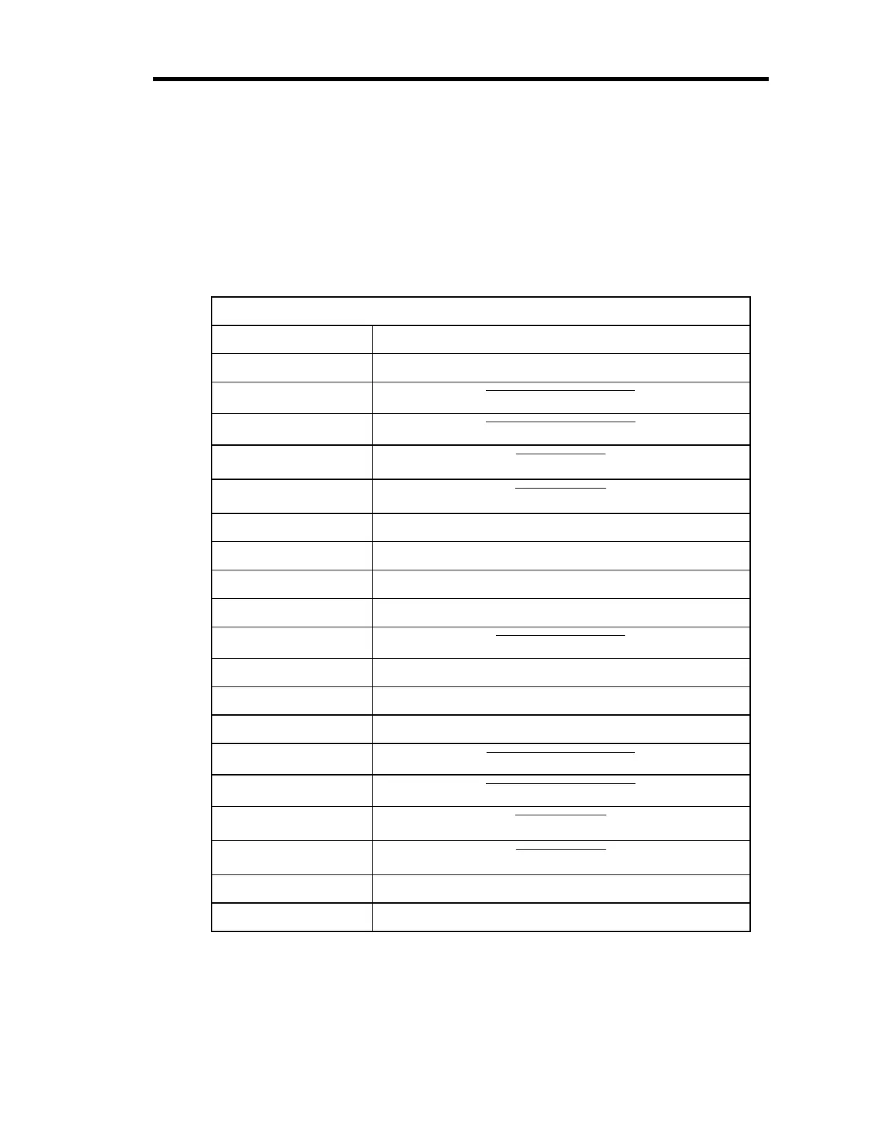
30 VDC. Table 21 lists the pinout functions of the General I/O connector.
General I/O Connector Pinout
Pin Number Assignment
1 Chassis
2
Remote Zero Channel 3
3
Remote Zero Channel 4
4
Latch Relay B
5
Latch Relay D
6 Digital Ground
7 Reserved
8 Reserved
9 Analog Output 1
10
Front Panel Lockout
11 Relay B Normally Open
12 Relay B Common
13 Relay B Normally Closed
14
Remote Zero Channel 1
15
Remote Zero Channel 2
16
Latch Relay A
17
Latch Relay C
18 Digital Ground
19 Reserved
Table 21: General I/O Connector Pinout
(Continued on next page)
Artisan Technology Group - Quality Instrumentation ... Guaranteed | (888) 88-SOURCE | www.artisantg.com