Chapter Two: Installation 146 Set U
35
6. Place the unit on a flat surface in its normal orientation, with the rear panel facing you.
7. Decide where the board will go.
We recommend that you do not move any boards already installed in the 146 unit.
Instead, install a new board in an unused slot. This avoids the situation where the
146 unit changes user-defined parameters to default parameters. Refer to
New
Configuration Warning Code,
on page 37, for more information concerning a
configuration change in the 146 instrument.
A. It is best to install all transducer boards in slots 1, 2, 3, or 4, whichever is the
lowest numbered slot available.
B. It is best to install the Control board in slot 5.
C. It is best to install the Auxiliary Output board in slot 4 or 5 if no Control board is
present. If a Control board is present, it is best to install the Auxiliary Output
board in slot 4.
8. Unscrew the two small screws holding the slot cover that corresponds to the board slot
you intend to use.
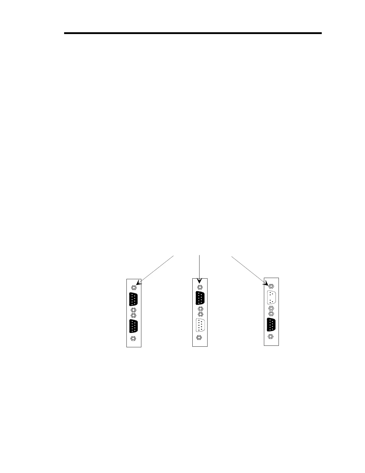
9. If your board has two Type “D” connectors (Dual Pirani, Dual Thermocouple, Control,
or Auxiliary Output boards), remove the top connector’s fastening screw.
Refer to Figure 10, page 35, for placement of the top connector’s fastening screw.
Dual Pirani or Dual Thermocouple
Board
Control
Board
Auxiliary Output
Board
Top Fastenin
Screws
Figure 10: Fastening Screw Positions
10. Slide the board inside the unit so that the connector(s) protrude through the opening in
the rear panel.
11. Line the board up so that the female connector on the board is directly over the male
connector on the mother board.
Artisan Technology Group - Quality Instrumentation ... Guaranteed | (888) 88-SOURCE | www.artisantg.com